Alignment and installation i – Elecraft KPA100 Manual User Manual
Page 44
44
Alignment and Installation
i
You will need two power supplies to complete testing of the
KPA100: the low-current supply that you use with your K2 at the 10-
watt level (3 amps minimum), and a 20-amp, 13.8 V supply for high
power use. The instructions will specify when to connect each power
supply.
Make the resistance measurements listed below, touching the
DMM's (+) lead to the indicated points, and the (-) lead to ground. Note:
The reading from J3 to ground may initially read a short (0 ohms) because
of the large electrolytic capacitor on the 12 V line. Use a low resistance
range, and wait up to 20 seconds for the reading to stabilize.
KPA100 Test Points (+)
Resistance
J3 + lead (red) (see note above)
> 5 k
Q1 collector
> 10 k
Q2 collector
> 10 k
Q1 base
11-16 ohms
Q2 base
11-16 ohms
J2 (antenna jack) center pin
> 10 k
Q9 tab (near rear panel)
> 10 k
D13 cathode (banded end)
> 10 k
Closely examine all of the cables on the left side of the KPA100.
Make sure the crimp terminals are properly seated, and that there are no
loose wire strands that might cause a short.
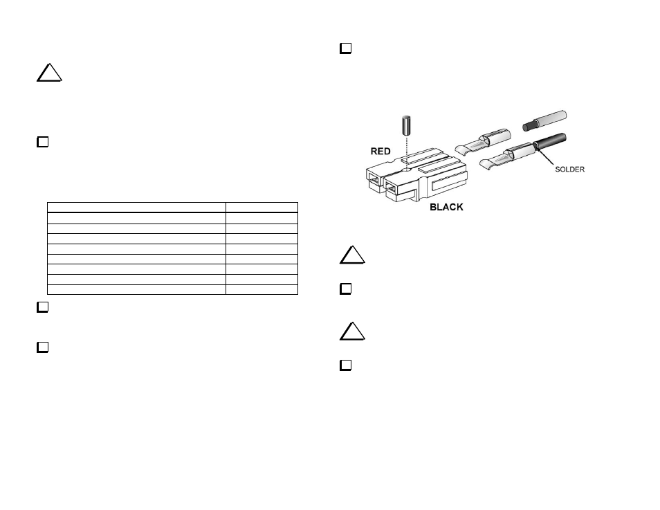
Locate two DC input connector housings, one red and one black.
Hold the two connectors in the orientation shown in Figure 37. Look
closely at the sides of the connectors. Each has a small tongue on the right
side, and a groove on the left.
Slide the tongue on the right side of the red housing into the groove
on the left side of the black housing. Make sure the housings are mated
exactly as shown, with the black housing to the right and the "hoods" at
the front of the connectors facing up. The interlocking tongue and groove
must be fully meshed.
Figure 37
i
Use only the supplied 12 AWG, 2-conductor stranded wire
(red/black) for the DC power cable.
Separate the two conductors at one end of the 12 AWG, 2-conductor
cable. Remove 5/16" (8 mm) of insulation from the red and black wires at
one end. Do not nick or cut off any of the strands.
i
Do not crimp the 30-amp terminals. They will be soldered in
the next step, providing a reliable connection.
Insert the wires into 30-amp terminals as shown above. Solder the
wires to the crimp terminals, using enough solder to completely surround
the wire and fill the interior of the terminal. (This may take as long as 10
seconds if you're using a small iron.) Be careful not to get solder on the
thin tongue that extends from the front of the terminal. It helps to tilt each
terminal so the tongue is above the solder cup so solder cannot run onto
the tongue.