Elecraft KPA100 Manual User Manual
Page 23
23
Store the top cover in a safe place to protect the finish.
i
You can easily remove the KPA100 and re-install the original top
cover at any time, returning the K2 to its low-power field configuration.
1
2
3
4
5
6
Figure 10
i
Before handling the Control board in the following steps,
touch a grounded surface.
Remove the screws that hold the K2 Control board to the front panel
board. Also remove the KAF2 audio filter board if present.
Use the long-handled Allen wrench supplied with the K2 to pry the
Control board up at the point marked "LIFT HERE" on the RF board.
Then unplug the Control board.
Place it in front of you with the
component side up.
Locate C42 on the K2 Control board (CTRL-C42), which is near
the voltage selector switch, S1. If the present value of this capacitor is .01
µF ("103"), replace it with an 0.1 µF capacitor ("104"). Use a capacitor
with 0.2" lead spacing. Note: If you have an older Control board (rev XC)
that does not include C42, solder the 0.1 µF capacitor between pins 4 and
8 of U3 (LMC6482, on the Control board).
i
A ribbon cable is used to connect the KPA100 board to the K2
Control board. To ensure correct cable orientation, keying inserts are
used. This requires cutting one pin on the male connectors at each end.
The pin to be cut, 8T (8-volt transmit), is not used by any Elecraft option.
If you need 8T for any reason, skip the next three steps, as well as the last
step on this page.
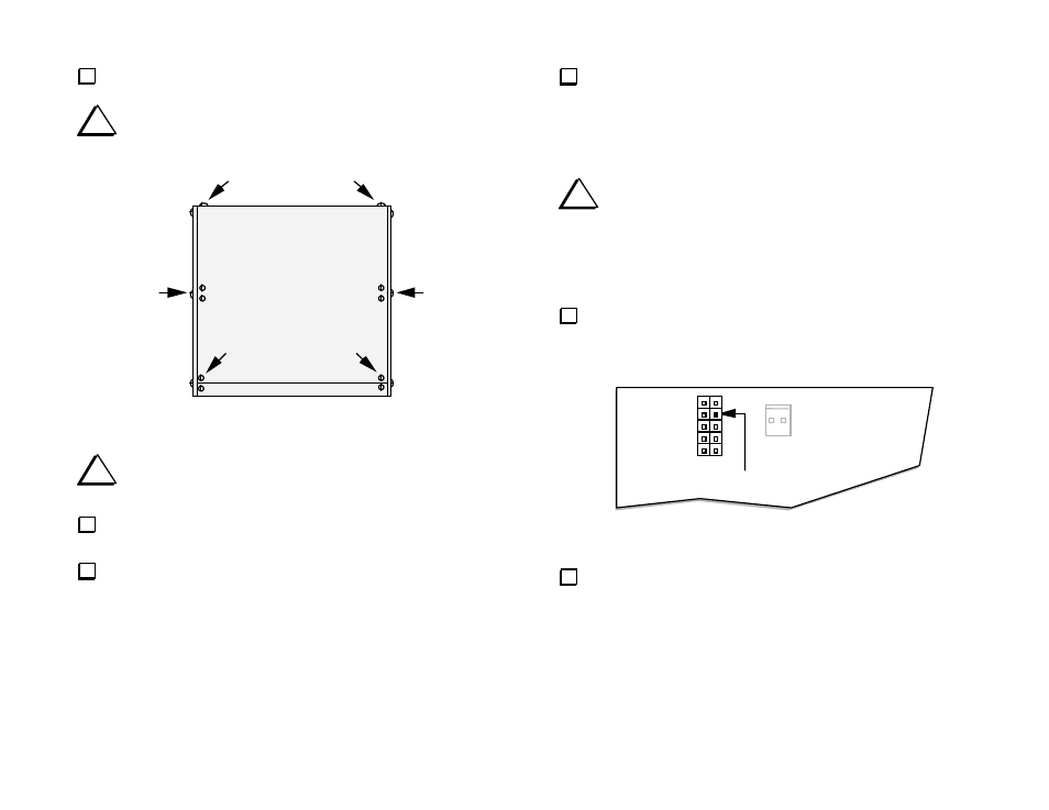
Locate P4 on the Control board, a 10-pin, dual row (5 x 2) male
connector (see Figure 11). P4's pins are numbered left to right, top to
bottom (pin 2 is to the right of pin 1, pin 3 is below pin 1, etc.).
Figure 11
Cut pin 4 of P4 as indicated above, as close as possible to the
connector's plastic body. The best way to do this is to grasp the pin with
long-nose pliers, then bend it repeatedly until it breaks off.
P4
Cut Pin 4
P5
1