Assembly, part ii – Elecraft KPA100 Manual User Manual
Page 27
27
Assembly, Part II
A number of toroidal inductors are used on the KPA100 PC board.
1
The
first inductor to be wound uses a type T50-10 core. The letter T identifies
this as an iron-powder core. 50 specifies the outside diameter in
hundredths of an inch, in this case 0.5 inches (12.7 mm). The -10 suffix
refers to the core type and color, in this case a black iron-powder core.
There are also two ferrite toroid cores used, such as type FT37-61. In this
part number, FT identifies the core as ferrite, and 37 is the size (0.37", 9.5
mm). The -61 identifies the type of ferrite, although all the ferrite cores
are dark gray in color. (There are also two "binocular" ferrite cores in the
kit, which will be described later.)
Three types of enamel wire are supplied with the kit: #22 red, #26 red,
and #26 green. #22 wire is much larger in diameter than #26. Be sure to
use only the type called for in the instructions; do not substitute other wire
types. Cut wires to the specified lengths to avoid running out of wire.
Eight black iron-powder toroid cores are supplied with the kit.
These are type T50-10 (0.5" [12.7 mm] dia.). Locate one of these cores
for use at L4. (Don't use the dull-gray FT50-43 core.)
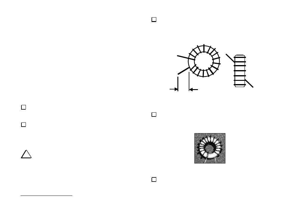
Find the component outline for L4, at the left side of the board near
relay K5. Compare this component outline to Figure 16, which shows two
views of a typical toroidal inductor. L4 will be mounted vertically as
shown at the right side of the drawing, with one wire exiting at the core’s
upper left, and the other at the lower right.
i
#22 enamel wire is fairly stiff, and may be difficult to wind
tightly onto the core. The turns should not be loose, but it is
acceptable to have a very small gap between the wire and the core's
flat surfaces. If you try to wind #22 so that it "hugs" the core all the
away around, you may have to pull the wire too hard, resulting in
hand fatigue.
1
Pre-wound toroids are available from an Elecraft-approved source; see page 3.
Cut 15 inches (37 cm) of #22 red enamel wire. To wind L4, "sew"
the long end of the wire through the T50-10 core. Each pass through the
core counts as one turn. 17 turns are needed, as shown in Figure 16. The
enamel insulation will be removed in a later step.
Remov e insu lation
Figure 16
Verify that the turns of L4 are not bunched together. They should be
evenly spaced, and should occupy about 80-90% of the core. Proper turns
spacing is shown in the photograph below (Figure 17).
Figure 17
Toroids shown in photos are wound on white cores to highlight turns
counts and spacing. Place L4 on top of the photo above, then adjust the
turns spacing until it is similar to that shown.