Elecraft KPA100 Manual User Manual
Page 46
46
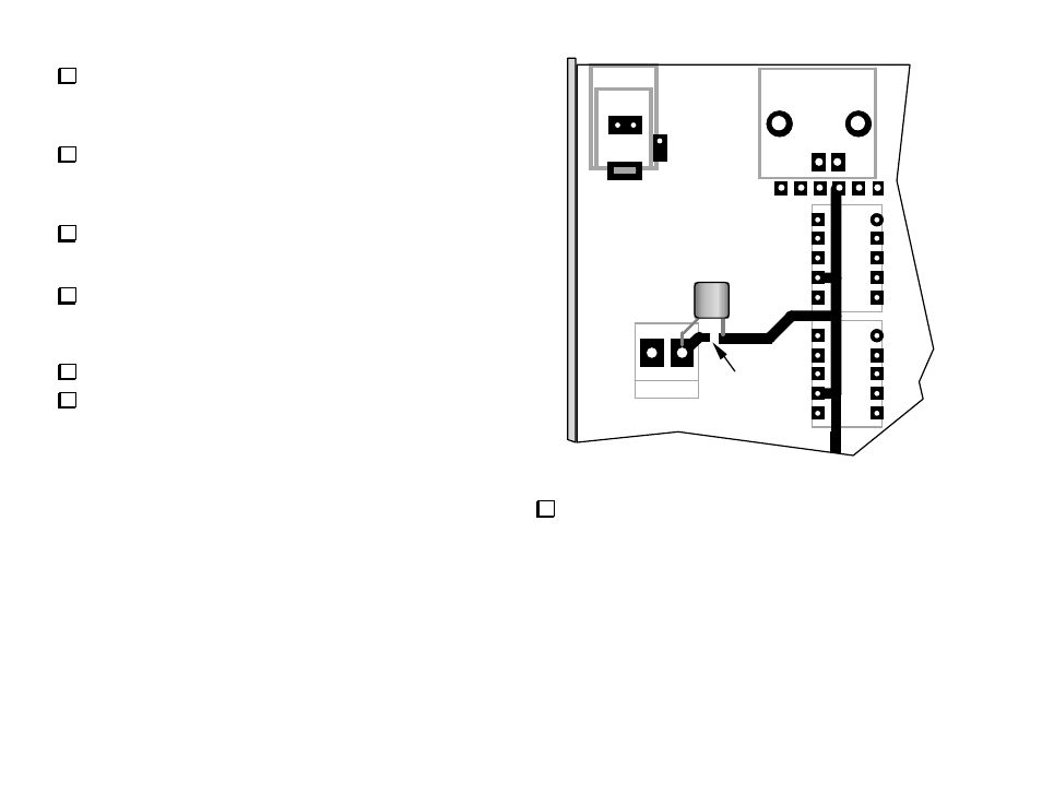
If your K2 serial number is 2999 or lower: Install the supplied DC
blocking cap (RF-Crf, .047 µF) on the bottom of the RF board at the
location shown in Figure 39. The indicated trace must be fully cut; verify
that it is open using your DMM.
Carefully examine all hardware associated with the PA transistors,
Q7 and Q8, on the bottom of the RF board. If any of the plastic hardware
or the thermal pads appears to be melted or damaged, you should order
the K2 PA Hardware Kit from Elecraft.
Re-install the heat sink/lower panel and any new Q7/Q8 hardware as
described in Part III of the basic K2 assembly instructions. Do not over-
tighten any of the hardware.
Using a DMM on its lowest resistance scale, measure resistance
from the collectors of Q7 and Q8 to ground. If you see a reading of less
than 100 Ω, the heat sink may be shorted to one of the transistor tabs.
Remove the heat sink and correct the short before proceeding.
Re-install and secure the 160-meter module if applicable.
Re-install the K2's bottom cover.
K10
J4
K9
P6
J3
Crf
Cut
Figure 39
Install the black rubber BNC connector cap on the K2's BNC
antenna jack. The BNC antenna jack will not be used once
the KPA100 is installed. The antenna will be connected to the
KPA100's SO239 jack instead, even when using low power.