J7 j2 e1 – Elecraft KPA100 Manual User Manual
Page 54
54
Verify that the two standoffs at the front edge of the KPA100 board
are 1/2" (12.7 mm) tall. The others should be 5/8" (16.9 mm).
Make sure that the 4-MHz crystal, X2, does not have any solder on
the top of the can. If the ground wire was installed on the top, it must be
moved to the side of the can, and all solder removed from the top using
desoldering braid. Otherwise the shield will not fit correctly.
Place the shield assembly onto the KPA100. The three spring clips
on the shield should face downward (toward the KPA100 PC board). The
spring clip in the rear should be touching bare metal at the inside of the
rear panel. When the shield is aligned with the 7 standoffs, this spring clip
should be slightly compressed.
If the shield doesn't lay flat against all of the standoffs, it may need
to be straightened. If you do attempt to straighten it, be careful not to
bend any of the spring clips.
Secure the shield assembly to the standoffs using 4-40 x 1/4" (6 mm)
pan head screws and split lock washers.
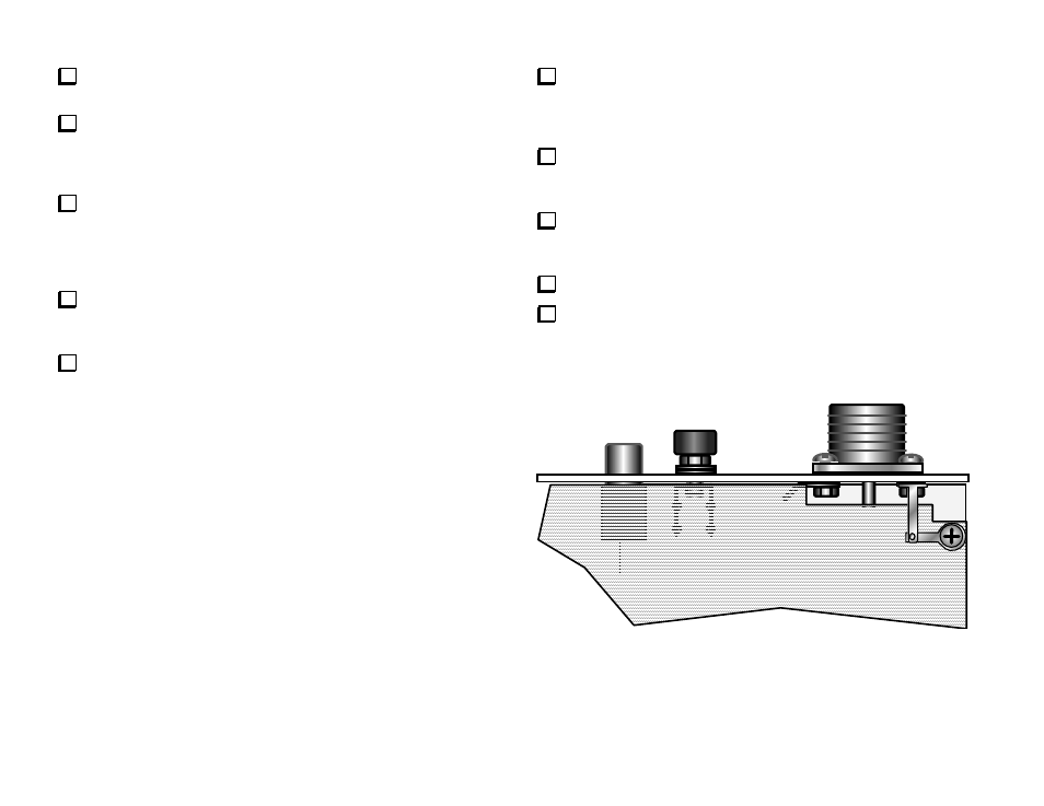
The two remaining solder lugs will be used to form a ground strap
between the shield and rear panel as shown in Figure 39a. Attach one lug
to the shield screw nearest the SO239 connector. The lug replaces the
lock washer, which can be saved as a spare.
Attach the second lug to the upper-right of the four screws holding
the SO239 connector to the rear panel. This lug also replaces the original
lock washer.
Using long-nose pliers, fold the second lug down at a 90-degree
angle so that it overlays the first as shown below. Trim the excess length
off the end of the first lug.
Solder the two lugs together.
Tighten the hardware to ensure good contact at both ends of the
ground strap.
J7
J2
E1
Figure 39a