Elecraft KPA100 Manual User Manual
Page 20
20
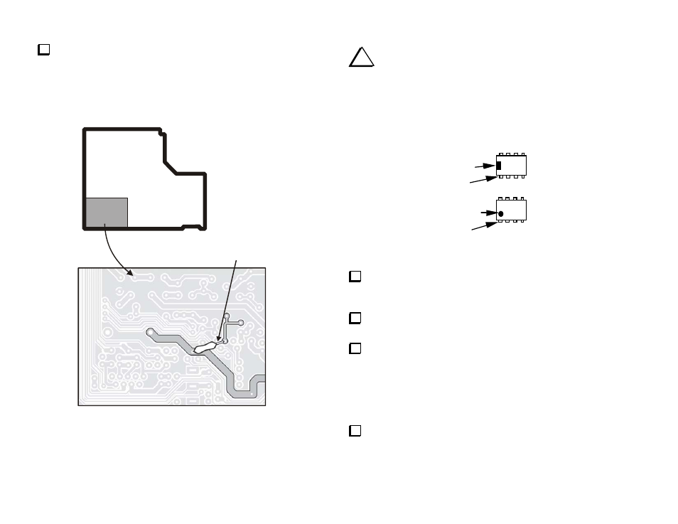
Mount R40 on the bottom of the PCB as shown in Figure 7. There is
no outline on the board for this resistor. Study the traces carefully to be
sure you have it positioned correctly. Position the resistor against the
board. The insulation is to ensure the bare lead cannot short to any of the
traces. If necessary trim the insulation slightly if it is too long. Solder to
the existing solder pads that are already occupied by leads. Trim the
resistor leads short so no excess lead extends beyond the solder.
22 K
Insulate exposed
lead (see text)
Enlarged
area
Bottom
of board
Figure 7
i
Before handling ICs, touch a metal surface. ICs damaged by
electrostatic discharge can become intermittent, and the resulting
problems may be difficult to troubleshoot.
Note: The pin 1 end of ICs can be identified by a notch or dimple as
shown in Figure 8. This end must be oriented toward the notched end of
the component outline.
Pin 1
Notch
Pin 1
Dimple
Figure 8
Install U5 (LM358, 8 pins), which is located on the top side of the
board, left of the "KPA100" label. A portion of the part number is printed
on the board under the IC ("358"). Do not solder yet.
Bend two opposite corner pins on the bottom side to hold the IC in
place. Solder all 8 pins (about 1 to 2 seconds per pin).
Install the ICs listed below. All are located to the right of U5.
Compare the part number on the IC to the number printed on the board,
and make sure that the pin 1 end is oriented correctly.
__ U2, TD62083
__ U6, EL5146
__ U4, MAX1406
__ U7, LMC6482
Install the 28-pin IC socket at U1. The notched end of the socket
must be aligned with the notched end of its outline.