Elecraft KPA100 Manual User Manual
Page 29
29
Place each of the low-pass filter toroids on its photo and adjust the
turns spacing so it is similar to that shown. Re-check turns counts and
core colors. (Each pass through the core counts as one turn.)
i
Good electrical contact between toroid leads and their pads is
critical for safe and reliable operation at high power levels. If you see
any indication that the solder is not binding well to a lead, remove the
toroid and prepare the leads again.
Install L1 vertically as indicated by its component outline (near relay
K3).
Install and solder the remaining low-pass filter toroids. Match each
of the low-pass filter toroids to its reference designator carefully.
Exchanging any of them will result in poor performance on two or more
bands.
On the bottom side of the board, check for continuity between the
pads of all the low-pass filter toroids. If you get a reading of > 1 ohm,
remove the toroid from the board and prepare the leads again.
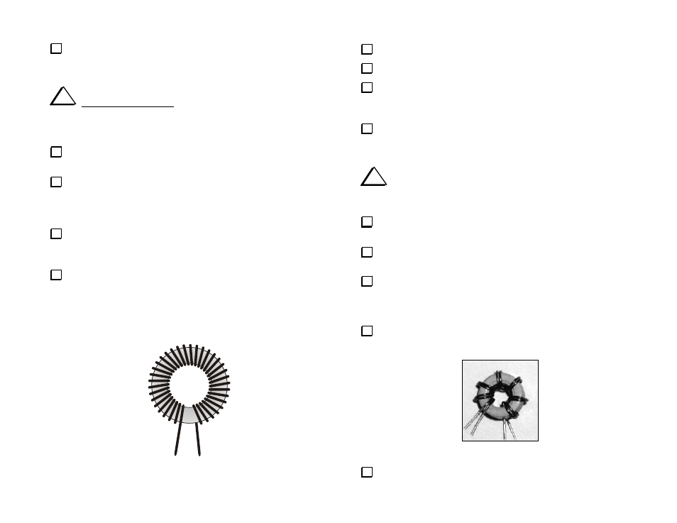
Prepare L16 and RFC1 as follows:
1. Use T50-1 cores: blue, 0.5" (12.7 mm).
2. Cut 26" (66 cm) lengths of #26 red enamel wire (the smaller
gauge red enamel wire) for each inductor.
3. Wind 37 turns on each core as shown in Figure 19.
Figure 19
Prepare the leads of L16 and RFC1 as before.
Install L16, located near relay K2.
Install RFC1, located near RFC1. Note that the outline for RFC1 is
for an in-line leaded part, not a toroid. RFC1 is a toroid. Place it within
the outline.
Locate the two dark gray (ferrite) toroid cores. The smaller of the
two (type FT37-61) has a diameter of 0.37" (9.5 mm). This core will be
used in the following steps.
i
Toroidal transformer T3 uses a bi-filar winding, which means
that two wires are wound on the core together. The wires will be twisted
together loosely before they're wound onto the core.
Cut two 8" (20 cm) lengths of #26 enamel wire, one red and one
green.
Twist the red and green wires together over their entire length. The
wires should cross over each other about every 1/2" (1 cm).
Wind 7 turns of the twisted wires onto the small ferrite core (FT37-
61). The turns should be spaced to cover about 80-90% of the core, as
shown in Figure 20 and Figure 21. Note: To make the turns spacing easy
to see, the wires shown in Figure 20 were not twisted together.
Separate T3’s leads as shown in Figure 21. The numbers on the leads
correspond to numbered pads on T3's PC board outline.
Figure 20
Strip and tin the leads of T3. (Figure 20 shows the leads tinned.)