Elecraft KPA100 Manual User Manual
Page 30
30
Keep the red and green leads spaced slightly apart during stripping and
tinning.
Using a magnifying glass, examine the red/green lead pairs to make
sure that the leads are not shorting together near the core.
Install T3 vertically on the PC board as indicated by its outline (near
the microcontroller, U1). Insert the red and green leads into their
numbered holes as shown in Figure 21. Pull the leads taut on the bottom,
then solder.
2
(RED)
3
(GRN )
1
(GRN )
4
(RED)
Figure 21
Verify continuity between the #1 and #4 pads of T3. If you get a
reading over 1 ohm, remove T3 and prepare the leads again.
Transformer T4 also uses a bifilar winding. Cut two 11" (28 cm)
lengths of #26 enamel wire, one red and one green. Twist the red and
green wires together as you did for T3.
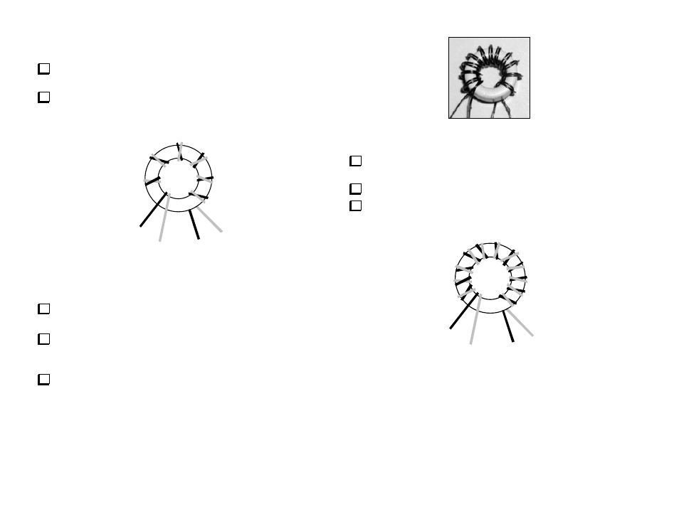
Wind 12 turns of the twisted wires onto the large ferrite core (FT50-
43). The turns should cover about 80-90% of the core, as shown in Figure
22 and Figure 23.
Figure 22
Separate T4’s leads as shown in Figure 23. The numbers on the leads
correspond to numbered pads on T4's PC board outline.
Strip and tin the leads of T4.
Using a magnifying glass, examine the red/green lead pairs to make
sure that the leads are not shorting together.
3
(RED)
2
(GRN )
1
(GRN )
4
(RED)
Figure 23