Elecraft KPA100 Manual User Manual
Page 19
19
MOSFET transistors Q6 and Q7 (ZVN4424) have a modified
TO-92 package that must be oriented as shown in Figure 5b. Some
ZVN4424's may be labeled on both sides, so you'll need to go by the
shape of the part: orient the larger flat side toward the flat side of the
outline. Install and solder Q6 and Q7, which are located between relays
K1 and K2.
Q9 is a TO-220 package MOSFET (IRF830 or IRL620) with a metal
tab. The tab may have been cut off already. If not, you'll need to trim it.
Using heavy wire cutters or tin snips, cut off most of the tab (see Figure
6). This is necessary to prevent the tab from shorting to the shield in later
steps. Do not use flush cutters or other small cutting tools to cut off
the tab; this may damage the tool.
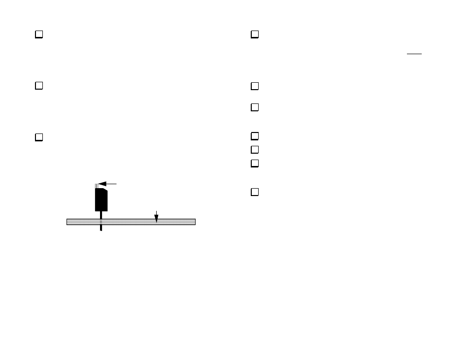
Install Q9 vertically as shown below. The transistor will sit above
the board due to the shoulders on the leads. The tab must be oriented
toward J7 as indicated by the component outline. Trim the pins on the
bottom after soldering.
Shortened Tab
Back edge of PCB
Figure 6
Transistor Q3 (MJE182) will be installed on the bottom side of the
board, near the board cutout for power transistor Q2. Place the transistor
over its outline, with the metal side of the package facing away from
the board. Bend the three leads at right angles to match the given pad
locations, but do not solder yet. Note: the leads will break if bent too
many times.
Insert Q3's leads into their holes. Center the transistor's plastic body
within its component outline. Re-form the leads if necessary.
Verify that Q3's metal side is facing away from the board, then
solder the leads from the top side, keeping the transistor pressed down
against the board.
Install Q4 in the same manner.
Locate R40, a 22K 1/4 W resistor (red-red-orange).
Make a 1/4” (6.3 mm) length of insulation by stripping a short
segment from one end of the red or black #20 insulated wire. Don’t use
the green #22. That insulation is too small.
Slide the insulation over one lead of R40 and position it against the
body of the resistor.