Ec b (a) (b) – Elecraft KPA100 Manual User Manual
Page 38
38
Using your DMM's lowest resistance scale, check for continuity (< 1
ohm) between one set screw and all of the others.
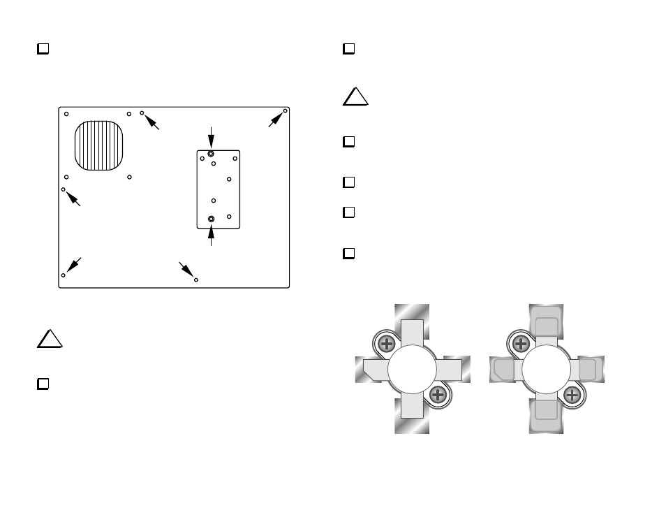
Pedestal
H
H
H
H
H
S
S
Figure 29
i
The leads of some components near the power transistors
must be flush-trimmed as explained in the next step. This will prevent
leads from shorting to the pedestal.
Flush-trim the leads of the components listed below on the bottom of
the board. The leads must be less than 1/32" (0.7 mm) long.
__ C40
__ C50
__ C80
__ C81
__ C58
__ C59
__ C31
__ L18 (jumper)
__ Z1
__ L16
Over the rest of the board, trim any component leads that you may
have missed earlier, including connector leads. Use a ruler to make sure
that all leads are trimmed to less than 1/8" (3 mm).
i
The PC board will be attached to the heat sink temporarily in
the next step. This will position the power transistors correctly for
soldering. Do not install thermal pads at this time.
Place the KPA100 PC board assembly on top of the heat sink.
Secure the board to the heat sink at the pedestal set screws using 1/2"
(12.5 mm) long standoffs. Thread them on hand-tight only.
Locate the two flange-mount power transistors. If the tabs are bent,
straighten them carefully using long-nose pliers.
Pre-tin the tabs of Q1/Q2 (top and bottom) with a small amount of
solder. Also pre-tin the pads for Q1 and Q2 on the PC board. A high-
wattage iron will be required to tin the emitter pads.
Place power transistors at Q1 and Q2, orienting the four tabs as
shown in Figure 30a. The notched tab must be aligned with the PCB
pad labeled "C" (collector).
E
E
C
B
(a)
(b)
Figure 30