Initial tests – Elecraft KPA100 Manual User Manual
Page 22
22
Visual Inspection
i
Nearly all problems with kits are caused by poorly-soldered
component leads or incorrectly-installed components. You can locate
and correct most assembly errors ahead of time with a simple visual
inspection. This is especially important at high power levels, where an
unsoldered or reversed component could cause damage to the power
transistors.
Verify that there are no parts installed at the following locations (In
addition to the following, there are other open spaces where parts will be
installed later as well) :
C82.
C83 (capacitor is mounted on the top of transformer T2).
L15.
R12.
Using a magnifying glass, examine the bottom of the PC board
closely for all of the following: cold solder joints (dull rather than shiny
appearance), solder bridges, and leads that are not soldered. Re-heat any
suspect joints.
Using the parts placement drawing at the end of the appendix,
re-check the orientation of all:
Diodes
Transistors
ICs
Initial Tests
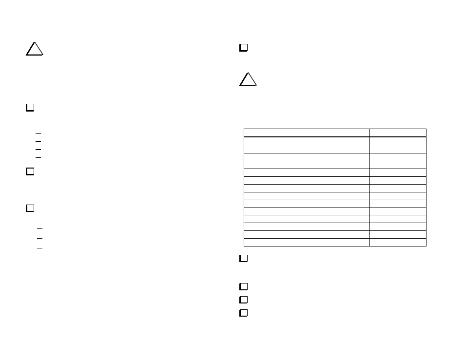
Make the resistance measurements listed below, touching the
DMM's (+) and (-) leads to the indicated points. The (-) lead will go to
ground in all cases except the first measurement (relay coils).
i
The symbol
>
means greater than. Your DMM may indicate
infinite resistance (all digits flashing) for readings that are listed as
"> 10 k." (Do not use an analog VOM.) Other readings should be
+/- 10 %. K4 reads higher resistance than the other relays because K3 is
not yet installed (the two coils are in parallel).
KPA100 Test Points (+, -)
Resistance
(+)
and (
-)
leads of relays K1,K2,K4-K12
(on bottom of board, marked)
650-800 (K4)
325-400 (others)
U1 pin 1, ground
> 1 k
U1 pin 2, ground
> 10 k
U1 pin 3, ground
> 10 k
U1 pin 4, ground
3.1 k
U1 pin 13, ground
> 10 k
U1 pin 14, ground
> 10 k
U1 pin 27, ground
> 10 k
U1 pin 28, ground
> 10 k
U4 pin 1, ground
> 10 k
U4 pin 8, ground
> 10 k
"AF" pad (measure from bottom), ground
> 10 k
D10 banded end, ground
> 10 k
Determine what revision of firmware your K2 has installed at
present by turning the K2 on while holding any switch. Record the
number shown at the left end of the LCD (e.g., 2.01H): _______.
Turn off the K2. Disconnect all external cables.
Remove the six K2 top cover screws shown in Figure 10.
Remove the top cover. Disconnect the speaker and all options.