Elecraft KPA100 Manual User Manual
Page 47
47
Set the KPA100 upside down to the right of the K2 on a suitable
platform, as you did earlier.
Connect a low-current (3 amp minimum) power supply to the K2's
DC barrel jack (RF-J3).
Plug in the ribbon between the KPA100 and the K2 Control board.
Turn on the K2. You should see the NO PA PS message as
before, since no power supply is connected at KPA100-J3.
Check the K2 current drain and voltage using the DISPLAY switch.
Current should be about 100-200 ma higher than without the KPA100.
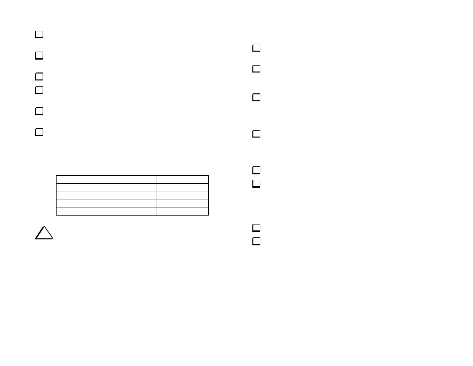
Set your DMM for DC volts, 200 or 300 V full scale (or auto
ranging). Connect the DMM's (-) probe to the ground jumper on the
KPA100 board (near U1). Using the DMM's (+) probe, make the voltage
measurements listed below.
KPA100 Test Point (+)
Voltage
Junction of C77 and R11
90 to 150 V
U4 (MAX1406) pin 8
-5 to -25 V
TP1 (near Q2 and T2)
0 to 0.1 V
J3 + lead (red)
0 V
i
If you have any difficulty during the test or alignment steps that
follow, refer to the Troubleshooting and Repair section of this
appendix.
Receiver Tests
Plug a pair of headphones into the K2's headphone jack. Turn on the
K2 and adjust the AF GAIN control so that noise can be heard.
Plug the audio cable from the KPA100 (J5) into the K2's internal
speaker jack (RF-P5). If this has any effect on the noise heard in the
headphones, you may have a short in the wiring of J5.
Unplug the headphones. You should now hear noise coming from
the KPA100's speaker. The sound may be reduced in volume (it will
sound normal when the KPA100 is installed inside the K2). If the signal
sounds distorted or very weak, check the wiring of the J5.
Plug the headphones (or a speaker) into the external speaker jack at
the back of the KPA100 (J6). You should hear the same signal as before,
and louder if you're using headphones. Note: If you're using stereo
headphones, you'll only hear the signal in one ear.
Turn the K2 off.
Connect the KPA100's internal RF cable (J1) to the K2, at RF-P6
(labeled "AUX RF"). Do not plug J1 into RF-P3 ("AUX 12V").
Note: Do not connect the KPA100's internal 12VDC cable (J4) to the K2
at this time.
Turn the K2 on.
Connect an antenna to the KPA100's SO239 antenna jack (J2).
Verify that you hear signals or atmospheric noise on all bands. You
should hear relays switching on the KPA100 as you change bands.
Note: The low-pass filter relays on the KPA100 will switch at different
bands than those on the K2 RF board. On the KPA100, 30/40, 17/20, and
10/12/15 meters each share a single low-pass filter.