Elecraft KPA100 Manual User Manual
Page 36
36
Locate the larger binocular coil form for use at T2. Note: T2 may
vary in length from 1" to 1 1/8" (25 to 29 mm). The given pads can
accommodate either length. Figure 27 shows all five of T2's pads.
3
2
1
5
4
Figure 27
Center T2 at its indicated location with the gap (bottom side) toward
the board. Contacts 1-3 must be aligned with their PCB pads.
i
Once T2 is installed, it is nearly impossible to remove. While
soldering T2, make sure it is centered directly over its component
outline and is seated flat against the board.
Using a heavy solder iron, solder contact 1 to its pad over just a
small portion of its length.
If T2 is not centered over its component outline, or is tilted, reheat
contact 1 and adjust T2's position.
Solder contact 3 over its full length.
Solder contact 2 over its full length. Keep the iron tip away from
nearby components, especially potentiometers R26 and R27.
Solder contact 1 over its full length.
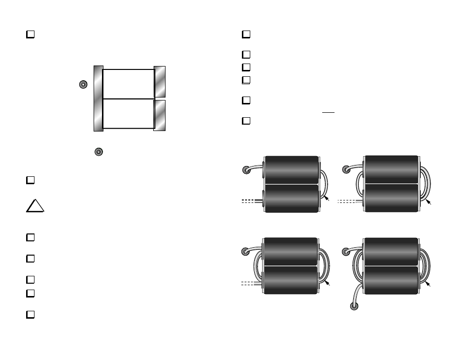
Cut an 18" (46 cm) length of #18 Teflon wire (gray). Remove 1/4"
(6 mm) of insulation from one end, then twist and tin the strands.
Solder the Teflon wire to the pad labeled T2-5.
Thread the wire through the core (1 turn) as shown in Figure 28a.
Add a second turn, pulling the wire so that the winding is tight. The
winding should look like Figure 28b (2 loops on the right).
Add two more turns (c), (d). Pull the wire to tighten the winding.
There should now be exactly four loops on the right side.
Cut the free end of the wire to a length of 1 1/4" (32 mm), measured
from where it exits the core. Remove 1/4" (6 mm) of insulation, then twist
and tin the strands. Solder the wire to T2-4.
4
5
5
5
5
(a)
(b)
(c)
(d)
1
2
3
4
Figure 28