Elecraft KPA100 Manual User Manual
Page 16
16
Install the 0.2" lead spacing capacitors listed below on the top side
of the board. Start with C11, which is along the front edge of the board
near the "KPA100" label.
__ C11, 0.1 µF (104)
__ C23, 0.1 µF (104)
__ C25, .001 µF (102)
__ C68, .01 µF (103) __ C89, .01 µF (103)
__ C26, 33 pF, 50V (Do not confuse with C5F, rated at 500 V or 1 KV)
__ C41, 100 pF (101)
__ C38, .01 µF (103)
__ C39, .01 µF (103)
__ C37, .01 µF (103)
__ C36, 0.015 µF (153, 15N)
__ C35, 0.1 µF (104)
__ C44, .01 µF (103)
__ C42, 0.015 µF (153, 15N)
__ C43, 0.015 µF (153, 15N)
__ C46, .01 µF (103)
__ C40, 0.1 µF (104)
Place relays at locations K1-K12, excluding K3. (K3 will be installed
after the output transformer, T2.) Each relay can only be installed one
way; the white mark on the relay must be oriented as indicated by the
mark on the component outline. Do not solder the relays yet, and do not
clip or bend the relay leads.
Inspect each relay to make sure that it is seated flat against the board.
If not, remove it and flush-trim the leads which are preventing it from
sitting flat against the board.
Make sure that you have not installed relay K3.
Using a hardcover book or other flat object to hold the relays in
place on the top side of the board, flip the board over. Solder two
diagonal corner pins on each relay.
Inspect the 11 relays closely to make sure that they’re seated flat
against the PC board. If not, re-heat the corner pins one a time while
pressing down on the relay. Once all relays are properly seated, solder the
remaining pins. Do not trim relay leads, which can cause mechanical
stress, reducing the life of the relay.
Install resistor network RP1 near the "KPA100" label at the front
edge of the board. The dotted (pin 1) end of RP1 should be oriented to the
left. (RP1 is symmetrical and can be reversed, but this orientation will
help visually identify the pin 1 end.)
Install trimmer potentiometers R26 and R27 (100 k, "104") near the
speaker cutout. The trimmers will sit a small distance above the PC board
on the pin shoulders. Set the trimmers to their midpoints.
Install trimmer potentiometer R6 (1 k, "102") at the right side of the
board near T1. Set the trimmer fully counter-clockwise.
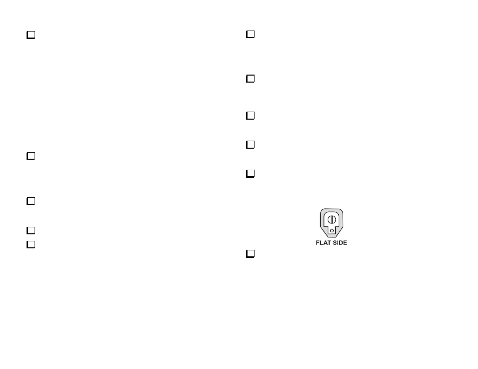
Install the 1 to 40 pF ceramic trimmer capacitors, C1 and C27. C1 is
at the far left near the small notch. C27 is near the microcontroller, U1
(16F872). Orient the flat side of each trimmer as indicated. Some
trimmers are more triangular in shape. Orient them as follows:
Using a small flat-blade screwdriver, set both trimmers to their
midpoints (screwdriver slot perpendicular to the flat side as shown
above).