Elecraft KPA100 Manual User Manual
Page 42
42
The 12V and RF cables to the K2 use identical connectors. In the
next section, a capacitor will be added to the RF board to prevent damage
to components in the event that the cables are reversed. In addition to this,
you should mark the 12 V connectors (KPA100-J4 and RF-P3) in some
way to distinguish them from the RF connectors.
Cut a 3" (7.5 cm) length of the 2-conductor speaker wire.
Split the conductors out at each end. Remove 1/4" (6 mm) of
insulation from all four wires, then twist and tin the strands using a small
amount of solder.
Near the speaker cutout on the KPA100 board you'll find two pads
labeled "SPKR" and "GND". Solder the silver-colored wire to the pad
labeled "SPKR", and the copper wire to "GND".
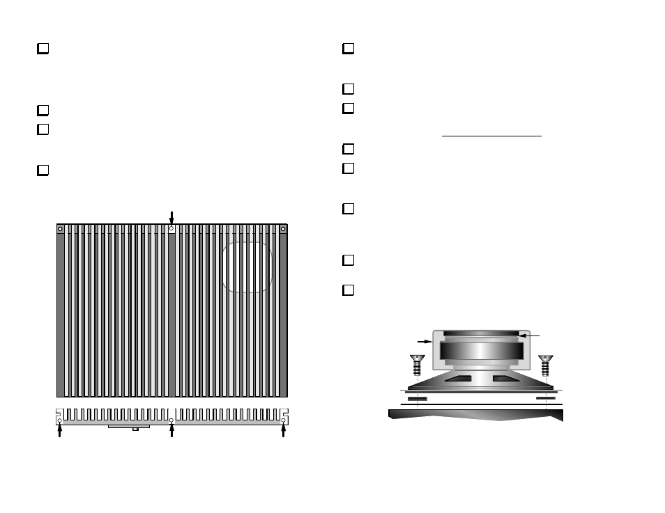
A
D
C
B
Figure 34
At this point you should have no unfilled component locations
except C82, L15 and R12. If others are unfilled, make sure no steps were
missed.
Unwrap the heat sink and place it on a soft, clean surface.
Using sand paper, remove the heat sink's black finish at the four
areas shown in white in Figure 34. At point A, be very careful to sand
only on the narrow shelf, not on the tops of the fins.
Trim the grille cloth to the same size as the speaker frame.
Place fibre washers (black) on each of the heat sink's four speaker
mounting holes. Cut just enough material off each corner of the grille
cloth so that it fits between the washers, not touching them.
Place the speaker on top of the grille cloth and fibre washers (Figure
35). Align the speaker frame with the front and side edges of the heat
sink. The speaker terminals should face the front, as shown in Figure
33 (previous page).
Secure the speaker using 4-40 x 3/16" (4.8 m) black, flat head
screws (Figure 35.) Do not use lock washers.
Locate the speaker shield. Remove the backing from the self-
adhesive pad inside the shield (Figure 35). Install the shield over the
speaker magnet, keeping it approximately centered.
Shield
Adhesive
Backing
Figure 35