13 top (a) (b) (c) – Elecraft KPA100 Manual User Manual
Page 34
34
Solder the red fan wire to the pad labeled "FAN+" (near J6). Solder
the black fan wire to the "FAN-" pad.
Route the fan wires away from RFC1.
Solder J2's wires to the points indicated in Detail A2 of Figure 24.
The red wire goes to T4 pin 5, black wire to the pad labeled "GND" near
E1, and bare wire jumper to T4 pin 6.
Examine the area around J2 closely to make sure that none of the
wires running to the center pin are touching nearby hardware.
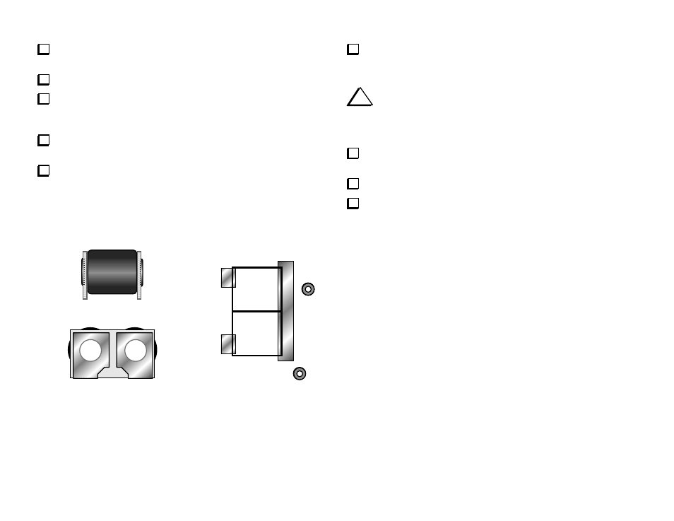
Locate the smaller binocular coil form for use at T1. As shown in the
side view, Figure 25a, the ferrite core is offset upward slightly, leaving a
gap at the bottom. The end view, Figure 25b, identifies contacts 1 and 3.
The other end is contact 2.
4
5
1
2
3
1
3
Top
(a)
(b)
(c)
Figure 25
Place T1 at its indicated location, with the gap (bottom side) toward
the PC board. Contacts 1, 2, and 3 must be aligned with their PCB pads.
Figure 25c shows all of T1's pads (1-5).
i
T1 is very difficult to remove once installed. While soldering,
make sure it is centered directly over its component outline and is
seated flat against the board. T1 may be just slightly larger or smaller
than the indicated outline.
Using a heavy soldering iron (pencil or gun), solder only contact 1
of T1 to the board. Solder over the full length of the contact.
If T1 is not centered, reheat contact 1 and adjust its position.
Solder contacts 2 and 3. Solder along the full length of each contact.