Elecraft KPA100 Manual User Manual
Page 45
45
Insert the terminals into the housings exactly as shown in Figure 37.
The terminals should snap securely into place. Pull on the wires
individually and make sure that they cannot be pulled out (if so, the
terminals are probably inserted upside down).
Optional: The supplied spring pin may be used to keep the red and
black housings from slipping apart (see above). The manufacturer of the
connectors recommends gluing the pin in place with super-glue.
i
You should install the supplied fuse holder even if your 20-
amp power supply has its own fuse or circuit breaker. This will allow
you to use the K2/100 transceiver with an unfused power supply or
battery if the need arises.
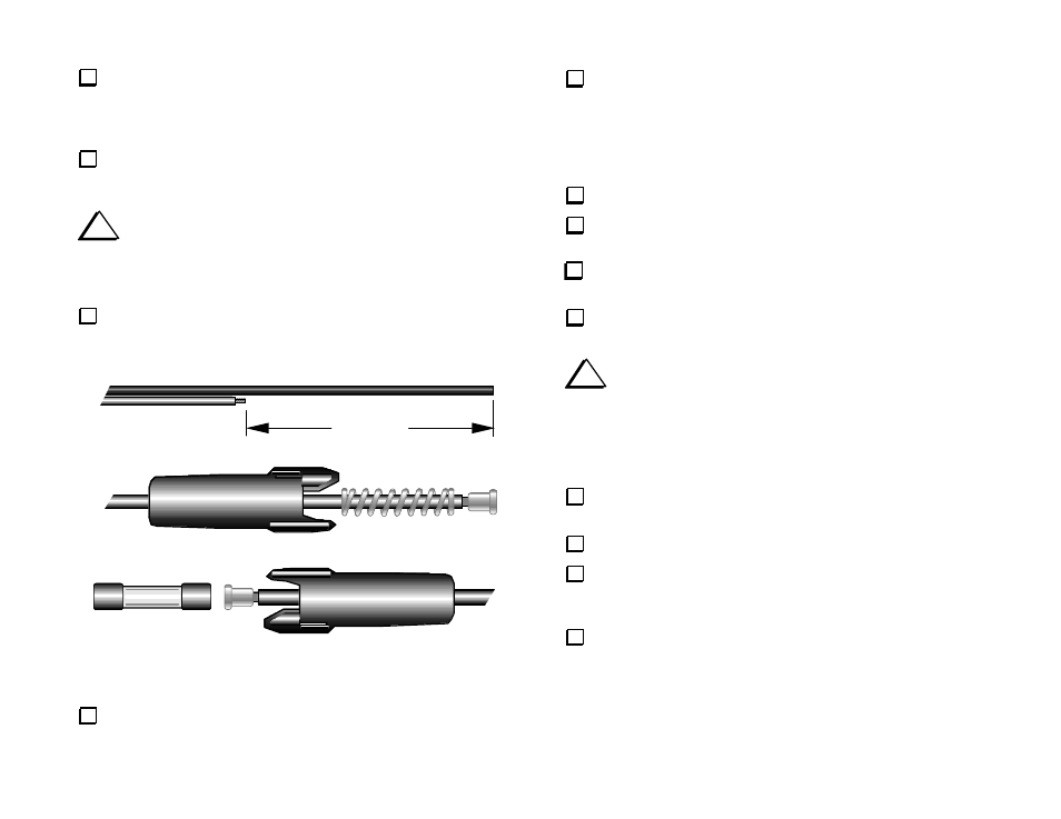
At the far end of the DC power cable, clip the red wire at the point
shown (Figure 38a). Peel away and save the short red wire.
8" (20 cm)
(a)
(b)
(c)
Figure 38
Peel the attached red wire back 3" (8 cm). Remove 5/16" (8 mm) of
insulation from the end (Figure 38a).
Insert the attached red wire through a fuse holder half, as well as the
spring (b). Note: If the wire won't fit into the fuse holder or spring, you
may need to peel off the thin, clear sleeve over the insulation. To remove
the sleeve, slit it lengthwise with a sharp tool, with the blade inserted
between the sleeve and the insulation. Be careful not to cut into the
insulation itself.
Solder the red wire to a fuse terminal.
Insert the 8" (20 cm) red wire through a fuse holder half. Remove
5/16" (8 mm) of insulation, then solder the wire to a fuse terminal (c).
Pull the terminals back inside the holder halves, and install the
supplied fuse (c). Press the two halves together and twist to secure.
Prepare the free end of the cable as needed to match your 20-amp
power supply connections.
i
At the far right edge of the K2 RF board are connectors P6 (Aux
RF) and P3 (Aux 12V). If you have not previously installed the KAT2 or
KBT2 options, you'll need to install the supplied 2-pin, 0.156" spacing
male connectors as described below. A DC blocking capacitor (RF-Crf)
has also been supplied, which will be installed only if your K2 serial
number is 2999 or lower.
If the 160-meter option is present, remove its one screw and unplug
it. Leave it (and the RX ANT jack) attached to the heat sink.
Remove the K2's bottom cover (6 screws).
Remove the K2's heat sink/lower rear panel (6 screws, two 4-40
nuts, and the nuts on the antenna and key jacks). Save the thermal pads
for Q7 and Q8, which may fall off when the heat sink is removed.
Install 2-pin male connectors at P6 and P3 as indicated by their
outlines. They must be oriented so that their plastic polarizing tabs
are toward the front panel of the K2. Solder P6 and P3.