Elecraft KPA100 Manual User Manual
Page 40
40
Cut a 6" (15 cm) length of two-conductor speaker cable (small
gauge, with clear insulation). Split the conductors at both ends, then
remove 1/4" (6 mm) of insulation from the ends of all four wires. Avoid
nicking or tearing the wire strands when removing the insulation.
Twist each wire's strands together, then tin the wires, using a very
small amount of solder (just enough to hold the strands together).
Attach crimp terminals to the two wires at one end as shown in
Figure 33 (Detail A). Before soldering, fold the small flaps of the terminal
closed using long-nose pliers. This will hold the wire in place.
i
When you insert crimp terminals into the housing in the next
step, they should snap into place. Each terminal has a small retaining tab
on the back that latches into a hole in the housing. The location of the
retainer and its hole in the housing are shown in Detail B.
Figure 33 shows J5 with the wires attached, and the small guides on
the connector facing down and away from you. Hold the connector in this
orientation, then insert the silver wire into the right hole of the housing
until it snaps into place. Insert the copper wire into the left hole. Verify
that the retainer tab is locked in place (Detail B).
Insert the wires at the other end of this cable into the pads labeled
AF (silver wire) and GND (copper wire) on the KPA100 board. Insert the
wires all the way up to the insulation to avoid leaving any exposed lead
length. Solder both wires.
Locate the two larger 2-pin housings and four of the large crimp pins
for use at J1 and J4.
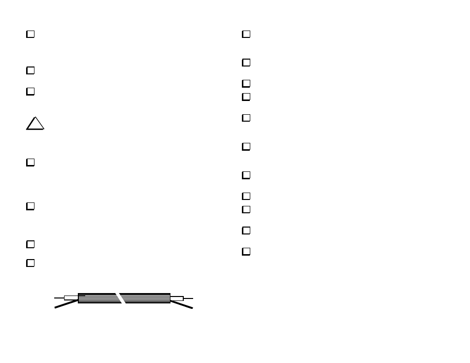
Cut a 4.5" (11.5 cm) length of RG-174 coaxial cable. Using a sharp
tool, remove about 3/4" (2 cm) of the coax jacket from each end (see
Figure 32). Be careful not to nick the braid.
Figure 32
Separate the braid (shield) from the center conductor at both ends.
Clip off about half the strands of the braid close to the jacket, then twist
the remaining braid into a thin bundle.
Remove a small amount of insulation from the center conductor. Use
long-nose pliers to hold the center conductor while stripping it.
Solder the center conductor and shield to crimp terminals.
Insert the terminals into a 2-pin housing as shown in Figure 33
(center conductor on the left, braid on the right).
Solder the other end of the coax cable to the two pads labeled "RF
IN" and "GND" on the KPA100 board (near relay K1). The shield goes
to "GND".
Cut two 4.5" (11.5 cm) lengths of #20 AWG stranded insulated
hookup wire, one red and one black. Remove 1/4" of insulation from
each end of both wires.
Twist the strands together tightly, then tin the wires. Use a very
small amount of solder.
Solder one end of each wire to a large crimp terminal.
Insert the terminals into a large 2-pin housing as shown in Figure 33
(black wire on the left, red wire on the right).
Solder the free end of the red wire to the pad labeled "12 K2" on the
KPA100 board. Solder the black wire to the nearby "GND" pad.
Use two cable ties to secure the wires at the indicated locations.