Elecraft KPA100 Manual User Manual
Page 14
14
The color bands on 1/4-watt 1% resistors can be difficult to read.
Use a DMM (digital multimeter) to verify the values of all these resistors.
Tape them to a piece of paper with their values labeled.
Install the resistors listed below on the top side of the board. Start
with R3, which is at the front edge of the board, near the "KPA100" label.
In general, assembly proceeds from left to right and from front edge to
back edge on the PC board.
__ R3, 2.7 ohms, 1/4 W (red-violet-gold)
__ R24 and __ R25, 8.45 k, 1%, 1/4 W (gray-yellow-green-brown)
__ R15 and __ R16, 3.3 k, 1/4 W (orange-orange-red)
__ R31, 200 ohms, 1 W (red-black-brown) or (201J)
__ R4, 100 k, 1/4 W (brown-black-yellow)
__ R10, 47 ohms, 1/4 W (yellow-violet-black)
__ R5, 15 k, 1/4 W (brown-green-orange)
__ R8, 10 k, 1/4 W (brown-black-orange)
__ R30, 3.09 k, 1% (orange-black-white-brown)
__ R32, 100 ohms, 1%, 1/4 W (brown-black-black-black)
__ R14, 470 ohms, 1 W (YEL-VIO-BRN) (located near back edge)
__ R11, 510 k, 1/4 W (green-brown-yellow)
__ R13, 100 ohms, 3 watts
__ R1, 3.3 k, 1/4 W (orange-orange-red)
__ R2, 2.7 ohms, 1/4 W (red-violet-gold)
__ R29, 3.3 k, 1/4 W (orange-orange-red), location: far left, near small notch
Sort all of the RF chokes by size and value. Do not pull on the leads,
which are fragile and can be easily damaged.
Locate a small 100-µH RF choke for use at RFC11 (BRN-BLK-
BRN color code, 0.4" lead spacing). Do not use one of the miniature 100-
µH RF chokes, which has a much smaller lead spacing.
Install RFC11 on the bottom side of the board. Its location is close
to the cutout for power transistor Q1.
Make sure RFC11 is pressed against the board as far as it will go,
then solder it from the top side of the board.
Install and solder the RF chokes listed below. Limit soldering time
on miniature chokes (2 to 3 seconds per lead). All chokes are on the top
side of the board near connectors J3 and J8. The body of RFC9 is slightly
longer than the spacing of the solder pads on the board. Bend the leads
under the body of RFC9 as needed to pass through the pads. RFC9 will
stand slightly above the board. That is normal.
__ RFC9, 15 µH, miniature (brown-green-black)
__ RFC6, __ RFC7, __ RFC8, 100 µH, miniature (brown-black-brown)
__ RFC4, __ RFC5, 15 µH, small (brown-green-black)
Locate miniature choke RFC3, 100 µH (brown-black-brown) and
resistor R33, 1k, 1/4 watt (brown-black-red).
Bend the leads of RFC3 to fit the pads on the board, but do not
install it yet.
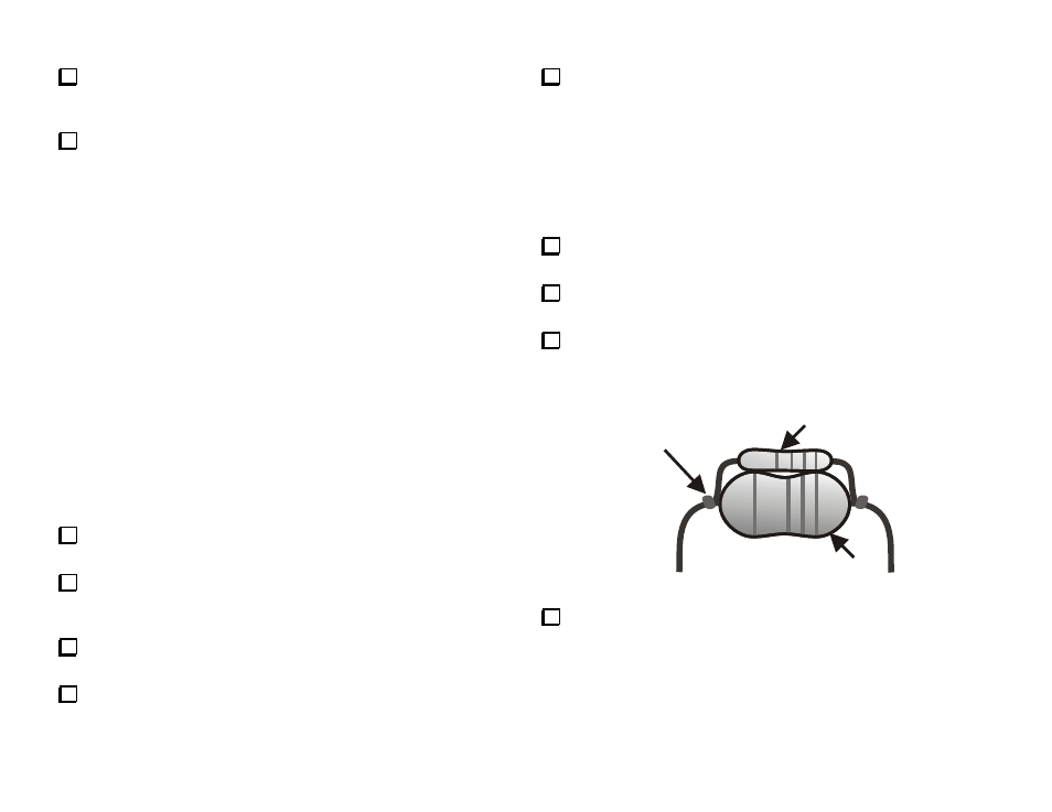
Mount resistor R33 on top of choke RFC3 as shown in Figure 3.
Wrap each resistor lead around the RFC lead next to its body once and
solder. Keep the soldering time short to avoid damaging the choke.
RFC3
R33
Wrap and
Solder at
Both Ends
Figure 3
Install the R33/RFC3 pair in the location marked RFC3 with the
choke against the board and the resistor above it. Solder and trim the
leads.