8x8 digitalmedia™ switcher crestron dm-md8x8 – Crestron electronic DM-MD8X8 User Manual
Page 28
8x8 DigitalMedia™ Switcher
Crestron DM-MD8X8
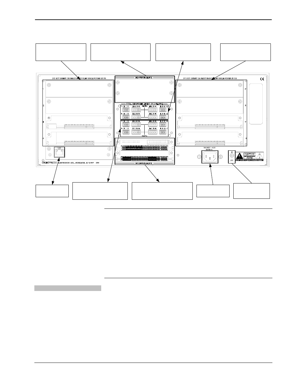
Hardware Connections for the DM-MD8X8, Rear
LAN:
10/100/1000 BASE-T
ETHERNET TO LAN
DM INPUT CARD SLOTS 5-8:
INSTALL CARDS TO RECEIVE
INPUT SIGNALS FROM AUDIO,
VIDEO, AND PC SOURCES
POWER:
FROM LINE
VOLTAGE
GROUND:
TIE ALL SOURCE AND
DEVICE GROUNDS TO
GROUND TERMINAL
DM INPUT CARD SLOTS 1-4:
INSTALL CARDS TO RECEIVE
INPUT SIGNALS FROM AUDIO,
VIDEO, AND PC SOURCES
DM OUTPUTS (SLOT 1):
INSTALL CARD TO TRANSMIT
DIGITALMEDIA SIGNALS TO
DIGITALMEDIA ROOM CONTROLLERS
DM OUTPUTS (SLOT 2):
INSTALL CARD TO TRANSMIT
DIGITALMEDIA SIGNALS TO
DIGITALMEDIA ROOM CONTROLLERS
DMNET PORTS (SLOT 1):
CONNECT TO DMNET RECEIVERS
AND SELECT INTERNAL OR
EXTERNAL POWER.
DMNET PORTS (SLOT 2):
CONNECT TO DMNET RECEIVERS
AND SELECT INTERNAL OR
EXTERNAL POWER.
NOTE: Ensure the unit is properly grounded.
NOTE: For optimum performance, Crestron strongly recommends using DM cable
or CresFiber fiber optic cable, available from Crestron. Other high-quality
CAT5e/STP wiring (such as CresCAT-D) or fiber optic cable (such as InfiniCor300)
may also be used with varying performance. Do not use low-skew CAT5e/STP
cable.
NOTE: When using fiber, it is recommended that you have at least two spare fibers
for each location. DigitalMedia fiber optic components use SC multimode
connectors.
DMNet Power
Devices connected to each DMNet port can receive power from the DM-MD8X8’s
internal power supply or from an external power supply such as the C2N-SPWS300.
To power a DMNet port using the DM-MD8X8’s internal power supply, install a
jumper on the EIG connector from the E (External) pin to the I (Internal) pin as
shown in the following diagram.
24
• 8x8 DigitalMedia™ Switcher: DM-MD8X8
Operations Guide – DOC. 6755A