8x8 digitalmedia™ switcher crestron dm-md8x8 – Crestron electronic DM-MD8X8 User Manual
Page 18
8x8 DigitalMedia™ Switcher
Crestron DM-MD8X8
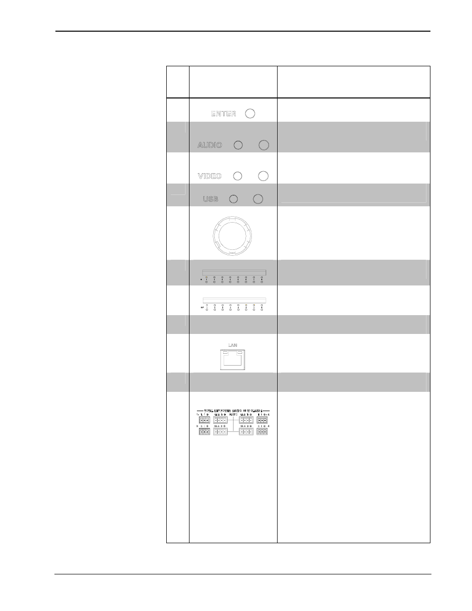
Connectors, Controls & Indicators (Continued)
#
CONNECTORS
1
,
CONTROLS &
INDICATORS
DESCRIPTION
8
ENTER BUTTON
(1) pushbutton, executes highlighted menu or
value
9
AUDIO BUTTON &
LED
(1) pushbutton & red LED, selects audio
routing view
10
VIDEO BUTTON &
LED
(1) pushbutton & red LED, selects video
routing view
11
USB BUTTON & LED
(1) pushbutton & red LED, selects USB
routing view
12
SELECTION KNOB
(1) Continuous turn rotary encoder, adjusts
menu parameters
13
IN 1-8
(8) pushbuttons and red LEDs, select input for
routing
14
OUT 1-8
(8) pushbuttons and red LEDs, select output
for routing
15
CARD SLOTS 1-8
(8) DM switcher input card slots; Accepts any
DM input card (each)
16
LAN
(1) 8-wire RJ-45 with 2 LED indicators,
10/100/1000BaseT Ethernet port; Green LED
indicates link status, Yellow LED indicates
Ethernet activity
17
DM OUTPUT SLOT
1 & 2
(2) DM switcher output card slots; Each slot
accepts (1) 4-channel DM output card
18
24ABG/EIG 1 – 4
(SLOT 1 – 2)
(8) sets of (1) 4-pin and (1) 3-pin 3.5 mm
detachable terminal blocks
Comprises (8) DMNet ports with “EIG” power
selection ports, each set associated with a
corresponding DM output port on the DM
output card in either DM output card slot;
Each DMNet port provides power and
communications for a DM device connected
via DM cable;
Each EIG port connects to an external power
supply
2
, or to the internal power source via a
jumper, to power the DM device connected to
the corresponding DMNet port;
Maximum Load: 75 Watts (3.13 Amps @ 24
Volts DC) per port, when connected to
external power supply
2
, otherwise limited to
available DMNet power
(Continued on following page)
14
• 8x8 DigitalMedia™ Switcher: DM-MD8X8
Operations Guide – DOC. 6755A