Crestron dm-md8x8 8x8 digitalmedia™ switcher – Crestron electronic DM-MD8X8 User Manual
Page 21
Crestron DM-MD8X8
8x8 DigitalMedia™ Switcher
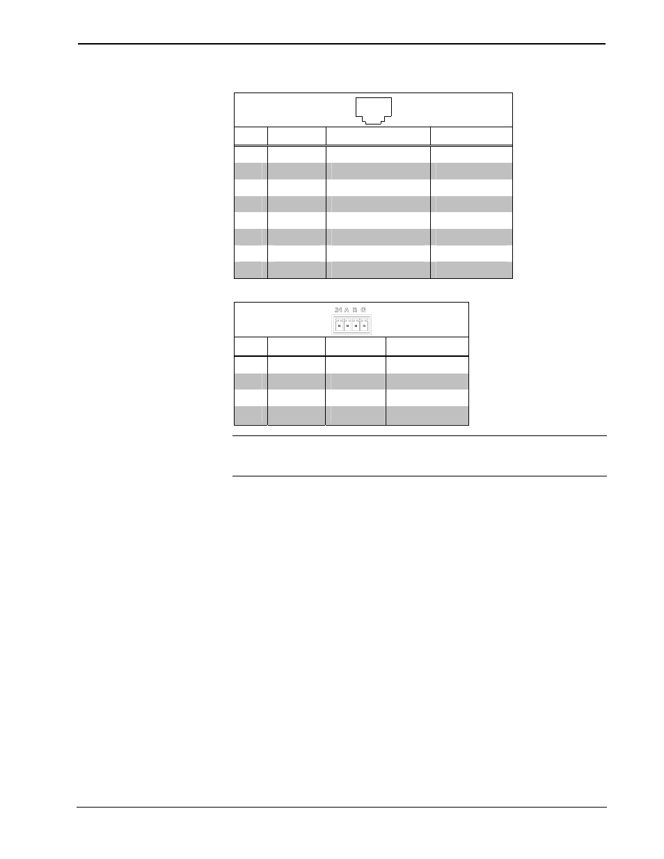
M Port Wiring
1
8
PIN SIGNAL
DESC.
WIRE
COLOR
1 +5V
+5V
Power
Orange/White
2
I2C_DATA
HDCP & EDID Data
Orange
3 E_TX-
10/100BaseT
Transmit Blue
6
E_TX+
10/100BaseT Transmit
Blue/White
4 E_RX-
10/100BaseT
Receive Brown/White
5
E_RX+
10/100BaseT Receive
Brown
7
I2C_CLK
HDCP & EDID Clock
Green/White
8
+5V_RTN
+5V Power Return
Green
24 A B G Port Wiring
PIN SIGNAL DESC. WIRE
COLOR
24 +24V
DC
Power Red
A
DM_NET+
DMNet
Orange
B DM_NET- DMNet
Grey
G
GND
DC Ground
Black
NOTE: Do not untwist the two wires in a single pair for more than 1/3-1/2”
(0.84-1.27 cm) when making a connection. The twists are critical to canceling out
interference between the wires.
The maximum transmission distances between repeaters are determined by the video
resolution sent over the wires. The total distance that video can be sent using
repeaters is shown in the following table for CAT5e/Shielded Twisted Pair (STP)
cable and DigitalMedia cable. While up to three repeaters may be used to extend the
transmission distance, the aggregate cable length of a signal path originating at a
DM-MD8X8 and terminating at a DM-RMC-100 DigitalMedia Room Controller
must not exceed 450 feet (137.1 meters) when using DigitalMedia cable (400 feet
(121.9 meters) when using CAT5E/STP cable). The following table shows the
maximum cable lengths allowed between repeaters when using DigitalMedia cable
or CAT5E/STP cable.
Operations Guide – DOC. 6755A
8x8 DigitalMedia™ Switcher: DM-MD8X8
• 17