Appendices ~ appendix c: control panel – ClearOne XAP400 User Manual
Page 108
102
Technical Services Group ~ 1-800-283-5936 (USA) ~ 1-801-974-3760
Appendices
~ Appendix C: Control Panel
6. Connect one connector terminator block to the Remote Panel on the
XAP/PSR unit. Route the other end of the cable through the back of the
electrical wall box and connect the terminator block to the Control Panel.
7. To use a second Control Panel, connect it to the unused Remote Panel
connector on the XAP/PSR unit or the unused connector on the first Control
Panel. You can daisy-chain up to six Control Panels to each Remote Panel
connector. Total cable run depends on the number of Control Panels used.
The distance information in the table at left is based on Cat. 5 cable with a
nominal resistance of 27ž per 1,000 feet (305 meters). All distances refer to
total cable runs from a single Remote Panel connector. For information
about extending beyond 800 feet (244 meters) total with six Control Panels,
call Technical Support at 1-800-283-5936.
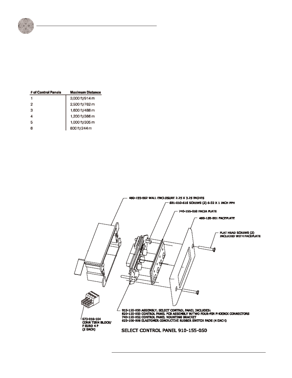
8. As shown in Figures C.5 and C.6, use the supplied pan-head screws to install
the Control Panel PCB assembly to the electrical wall box.
9. To install the facia plate, position it over the conductive rubber switch pads
on the PCB assembly, as shown in Figures C.5 and C.6.
10. Mount the faceplate over the rubber switch pads, using the two flat HD
screws.
Figure C.4. Control panel distance chart
Control Panel Assembly
Dimensions (both versions):
1.8"/4.6cm W x 4.125"/
10.5cm L (not including faceplate
or electrical box).
Figure C.5. Select Control Panel Assembly