ClearOne Converge Pro User Manual
Page 46
41
CONVERGE USB
Refer to the following diagrams and descriptions describe the CONVERGE USB connections and controls when
used as an USB interface and as and E-bus extender.
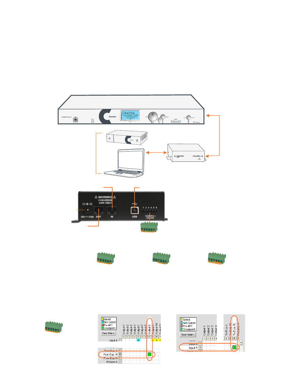
CONVERGE USB Interface Connections
Connect each CONVERGE USB unit to the site via the E-bus connections.
E-bus LINK IN from Stack
E-bus LINK OUT
(Not required if unit is at end of stack)
USB Connection to PC/Laptop or COLLABORATE Room
(Not required if used as an E-bus Extender)
12V DC
Power
Input
Terminal Block for Channel Selection
(Not required if used as an E-bus Extender)
COLLABORATE Room
VC Endpoint
or
Laptop/PC Running
UC Application
USB
Audio
Transmit and Receive
E-bus
From
LINK Out
E-bus To
LINK In
CONVERGE USB
CONVERGE Pro Unit
The E-bus channels upon which the Tx/Rx audio will be available is determined by the jumpers placed in the
Channel Selection Terminal Block.
Tx channel - K
Rx channel - L
Tx channel - M
Rx channel - N
Tx channel - O
Rx channel - P
Tx channel - Q
Rx channel - R
No
Connector
Routing the CONVERGE USB Interface Connections
Using CONVERGE Console, route each CONVERGE USB Tx/Rx signal within the site to match the E-bus
connections as selected by the terminal block. This is done on the Matrix screen for the site.
In the example below a terminal block jumper is between pins 1 and 6, so the CONVERGE Pro channels are M for
transmit and N for receive. These must then be routed to the desired inputs and outputs. The following two screen
captures show audio from the CONVERGE USB on Channel M going to Output 8, and Channel N receiving audio
from Input 9 then sending it to the CONVERGE USB.
Tx channel - M
Rx channel - N