ClearOne Converge Pro User Manual
Page 187
182
User-Definable Pins
The user-definable pins provide control via contact closure, and status via open collector functions in the unit. There
are two user-definable pins on the B port of every unit. The number of user-definable pins on the A port varies by
model, as summarized in the following table:
Model
User-Definable Pins
Control/Status Port A
User-Definable Pins
Control/Status Port B
880
16
2
880T
16
2
880TA
16
2
840T
20
2
8i
16
2
TH20
24
2
VH20
24
2
SR 1212
16
2
SR 1212A
16
2
Default Pin Assignments
For default pin assignments for Control/Status ports by model, refer to Appendix B.
Control/Status Ports
Control/Status A and B ports are female DB25 connectors used for General Purpose Input/Output (GPIO)
interactions between CONVERGE/CONVERGE Pro devices and external control devices such as wall switches and
push-to-talk microphones. Control programming enables external control devices and controller software to access
the CONVERGE/CONVERGE Pro serial command set, including common functions such as volume control, muting,
room combining, and running presets.
For more information on Control/Status Port A and B and other physical connections, see Controls and
Connections.
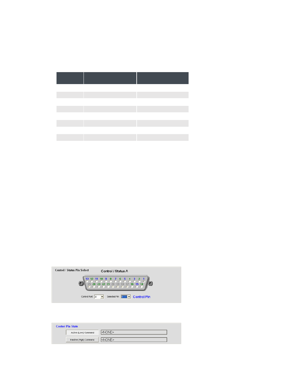
Control/Status Pin Programming
Use the following procedure to program user-definable pins:
1.
In the Control/Status Pin Select section of the screen, select port A or B from the Control Port drop-down
list.
2.
Select the pin you want to configure from the Selected Pin drop-down list. (Pin 1 is selected by default for
Control Port A and Pin 21 is selected by default for Control Port B.)