Rockwell Automation 1768-L45S Compact GuardLogix Controllers User Manual
Page 21
Rockwell Automation Publication 1768-UM002C-EN-P - April 2012
21
Install the Controller
Chapter 2
Follow these requirements to determine proper placement of your 1768
controller, power supply, 1768 I/O modules, and 1769 I/O modules:
•
Place the 1768-L4
xx controller so that it is the last module (furthest away
from the power supply) in the 1768 backplane.
•
The 1768 CompactLogix power supply distributes power from the right
side of the supply and must be the leftmost module in the system.
•
The local bank is powered by a 1768 power supply.
•
Up to eight 1769 I/O modules can reside in the local bank.
•
1768 slots are numbered right to left, starting with the controller as slot 0.
•
Up to two remote banks of 1769 I/O modules may be connected by using
1769-CRL
x extension cables.
•
Remote banks are powered by a standard 1769 power supply.
•
Each I/O bank must have its own 1769 power supply.
•
1769 slots are numbered from left to right, starting with the controller as
slot 0.
IMPORTANT
CompactLogix System Distance Ratings
Because the 1768 CompactLogix power supply works with the controller to
power a 1768 system, the distance rating in a 1768 CompactLogix system
differs from that in a 1769 CompactLogix system.
In the 1768 system, the distance rating is the distance between 1769 I/O
modules and the controller. In the 1769 system, the distance rating is the
distance between 1769 I/O modules and the power supply.
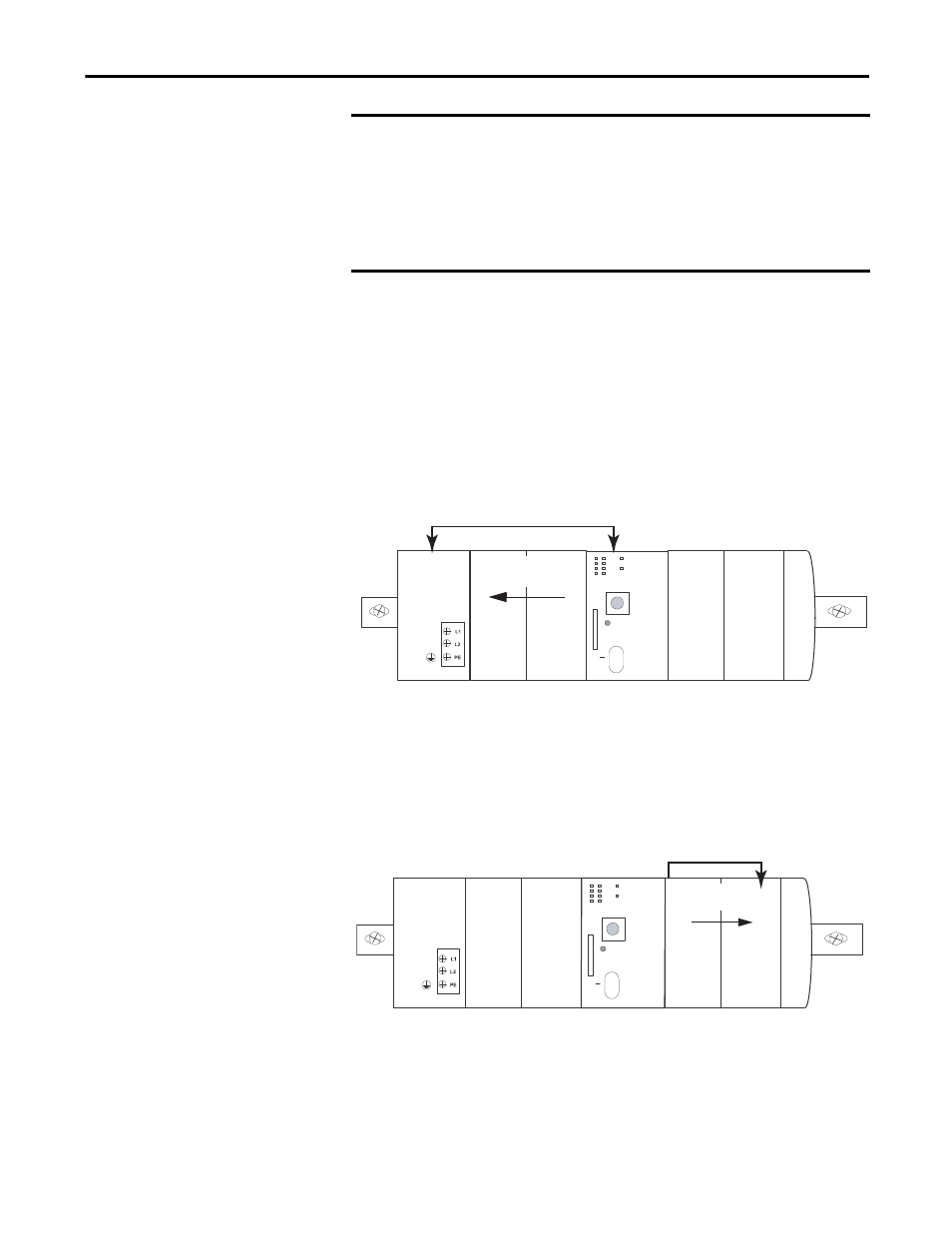
1768 Backplane
1768 Modules
1768-L43S
Slot 2
Slot 1
Slot 0
1769 Backplane
1769 Modules
1768-L43S
Slot 2
Slot 1
Slot 0