Through-hole socket mount system (inmate) – Vicor Micro Family of DC-DC Converter User Manual
Page 78
Design Guide & Applications Manual
For Maxi, Mini, Micro Family DC-DC Converters and Configurable Power Supplies
Maxi, Mini, Micro Design Guide
Rev 4.9
vicorpower.com
Page 77 of 88
Apps. Eng. 800 927.9474
800 735.6200
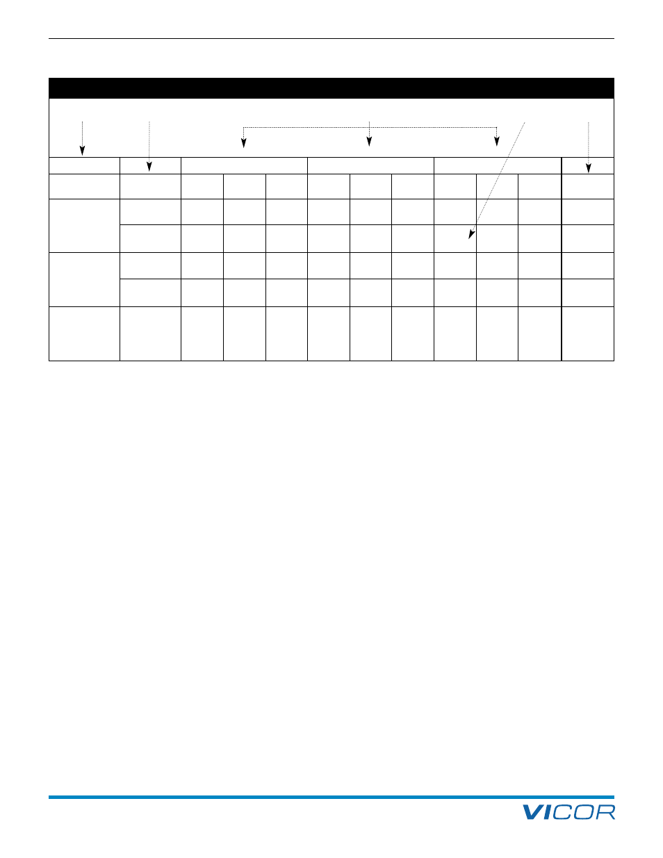
16. Through-hole Socket Mount System (InMate)
Board Thickness
Full Brick (Maxi)
Half Brick (Mini)
Quarter Brick (Micro)
Norm.
Mounting
Input
Output
5 Sets
Input
Output
5 Sets
Input
Output
5 Sets
Pin
(Min. / Max.)
Style
Style
0.062"
Inboard
18374
18382
18362
18374
18384
18366
18376
18386
18370
S or F
(
0.055"/ 0.071")
1,5 mm
Onboard
18378
18388
18364
18378
18390
18368
18380
18392
18372
N or G
(
1,4 mm /1,8 mm)
0.093"
Inboard
18375
18383
18363
18375
18385
18367
18377
18387
18371
S or F
(
0.084"/ 0.104")
2,4 mm
Onboard
18379
18389
18365
18379
18391
18369
18381
18393
18373
N or G
(
2,1 mm /2,6 mm)
0.125"
Onb oard
21539
21543
21510
21539
21544
21511
21540
21545
21512
N or G
(
0.1125"/0.1375")
3,1 mm
(
2,8 mm /3,5 mm)
1.
Select Board Thickness.
Nominal 0.062"(1,5 mm), 0.093"(2,4 mm) or
0.125"(3,1 mm).
2.
Select Mounting Style.
Inboard requires a PCB cutout for the “belly”
of the module. See dotted lines in PCB drawing
links on Page 80 for cut out area.
3.
Identify Module Type.
Full brick (Maxi), half brick (Mini) or
quarter brick (Micro).
4.
Select the Ordering Part Number.
Order packages of five input / output sets or in higher
quantities order input and output InMates separately.
For individual input or output InMates, minimum
orders of 35 for Maxi or Mini and 40 for Micro apply.
5.
Verify Correct Pin Style for the Module.
For predefined parts, “S” or “F”= short ModuMate
and “N” or “G”= long ModuMate
See Table 16–4 for standoff recommendations.
2.
3.
5.
1.
4.
Table 16–1 — Guide to InMate selection
InMate: Through-hole Sockets