Current sharing in power arrays – Vicor Micro Family of DC-DC Converter User Manual
Page 22
Design Guide & Applications Manual
For Maxi, Mini, Micro Family DC-DC Converters and Configurable Power Supplies
Maxi, Mini, Micro Design Guide
Rev 4.9
vicorpower.com
Page 21 of 88
Apps. Eng. 800 927.9474
800 735.6200
5. Current Sharing In Power Arrays
In general, it is not recommended to mix and match con-
verters, especially those with incompatible current-sharing
schemes. The droop-share method, however, is more
forgiving in this regard than with any of the other
methods. Current sharing can be achieved using arrays
constructed from different converter models or even from
different suppliers with a little external circuitry.
Driver / Booster Arrays. Most Vicor converters can
employ the driver / booster array for increased power.
(Figure 5–2) Driver / booster arrays usually contain one
intelligent module or driver, and one or more power-train-
only modules or boosters. The driver is used to set and
control output voltage, while booster modules are used
to increase output power to meet system requirements.
Driver / booster arrays of quasi-resonant converters with
identical power trains inherently current share because
the per-pulse energy of each converter is the same. If the
inputs and outputs are tied together and the units have
the same clock frequency, all modules will deliver the
same current (within component tolerances). The single
intelligent module in the array determines the transient
response, which does not change as modules are added.
Booster modules require only one connection between
units when their outputs are connected; no trimming,
adjustments, or external components are required to
achieve load sharing. The load sharing is dynamic and
usually guaranteed to be within five percent.
It is important to remember that when using boosters, the
input voltage, output voltage, and output power of the
boosters must be the same as the driver.
The advantages of driver / booster arrays are that they
have only a single control loop so there are no loop-within-
a-loop stability issues, and they have excellent transient
response. However, this arrangement is not fault tolerant.
If the driver module fails, the array will fail to maintain its
output voltage.
Analog Current-Share Control. Analog current-share
control, typical of PWM type converters, involves
paralleling two or more identical modules, each
containing intelligence. The circuit actively adjusts the
output voltage of each supply so that the multiple
supplies deliver equal currents. This method, however, has
a number of disadvantages. Each converter in the array
has its own voltage regulation loop, and each requires a
current sensing device and current control loop.
Analog current-share control supports a level of redundancy,
but it is susceptible to single-point failures within the
current-share bus that can, at best, defeat current sharing,
and, at worst, destroy every module in the array. The
major reason for this is the single-wire galvanic connection
between modules.
Return
+S
+OUT
SC
–S
–OUT
–IN
PR
PC
+IN
+S
+OUT
SC
–S
–OUT
–IN
PR
PC
+IN
DC-DC Converter
Maxi or Mini
+IN
– IN
+OUT
DC-DC Converter
Maxi or Mini
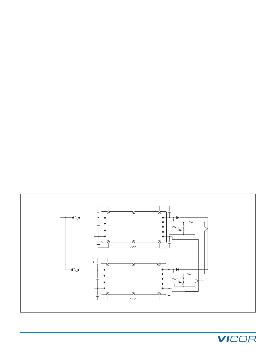
Figure 5–1
—
The droop-share method artificially increases the output impedance to force the currents to be equal.