Filter / autoranging rectifier module (farm), Example – Vicor Micro Family of DC-DC Converter User Manual
Page 40
Design Guide & Applications Manual
For Maxi, Mini, Micro Family DC-DC Converters and Configurable Power Supplies
Maxi, Mini, Micro Design Guide
Rev 4.9
vicorpower.com
Page 39 of 88
Apps. Eng. 800 927.9474
800 735.6200
8. Filter / Autoranging Rectifier Module (FARM)
In this example, the output required from the DC-DC
converter at the point of load is 12 Vdc at 320 W.
Therefore, the output power from the FARM would be
375 W (assuming a converter efficiency of 85%). The
desired hold-up time is 9 ms over an input range of
90 to 264 Vac.
Determining Required Capacitance for Power Fail
Warning. Figure 8–8 is used to determine capacitance
for a given power fail warning time and power level,
and shows that the total bus capacitance must be at
least 820 µF. Since two capacitors are configured in
series, each capacitor must be at least 1,640 µF.
NOTE: The warning time is not dependent on line
voltage. A hold-up capacitor calculator is available on
the Vicor website, at
Determining Ride-through Time. Figure 8–9 illustrates
ride-through time as a function of line voltage and output
power, and shows that at a nominal line of 90 Vac, ride-
through would be 68 ms. Ride-through time is a function
of line voltage.
Determining Ripple Voltage on the Hold-up
Capacitors. Figure 8–10 is used to determine ripple
voltage as a function of operating power and bus
capacitance, and shows that the ripple voltage across
the hold-up capacitors will be 12 V p-p.
Determining the Ripple on the Output of the
DC-DC Converter. Figure 8–11 is used to determine the
ripple rejection of the DC-DC converter and indicates a
ripple rejection of approximately 60 dB for a 12 V output.
Since the ripple on the bus voltage is 12 Vac and the
ripple rejection of the converter is 60 dB, the output
ripple of the converter due to ripple on its input (primarily
120 Hz) will be 12 mV p-p.
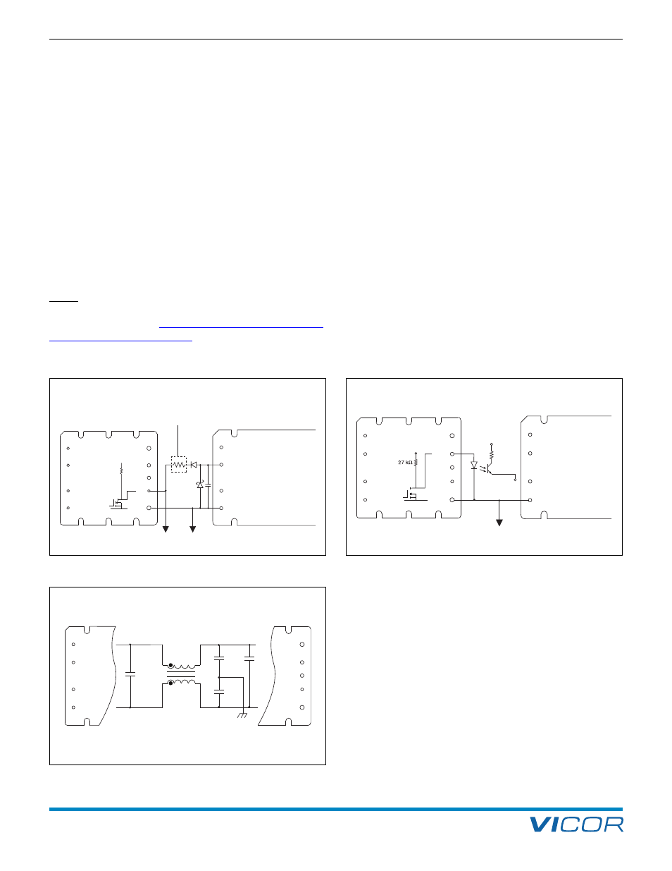
+IN
PC (GATE IN)
PR
–IN
N
EMI GND
N/C
L
+
EN
–
150 k
15 Vdc
Micro-
controller
Vicor DC-DC
Converter
FARM
BOK
ST
Not used with VI-260/VI-J60
+IN
PC
PR
–IN
N
EMI GND
N/C
L
+
BOK
ST
EN
–
Vicor DC-DC
Converter
Micro-
controller
15 Vdc
+5 Vdc
Secondary
referenced
4.7 nF
L1
4.7 nF
N
EMI GND
N/C
L
0.47
µF
0.099
µF
330
µH
+
BOK
ST
EN
–
CM
Figure 8–4 — Enable (EN) function
Figure 8–5 — Bus OK (BOK) isolated power status indicator
Figure 8–6 — Internal filter
EXAMPLE