Output ripple attenuator module (microram) – Vicor Micro Family of DC-DC Converter User Manual
Page 61
Design Guide & Applications Manual
For Maxi, Mini, Micro Family DC-DC Converters and Configurable Power Supplies
Maxi, Mini, Micro Design Guide
Rev 4.9
vicorpower.com
Page 60 of 88
Apps. Eng. 800 927.9474
800 735.6200
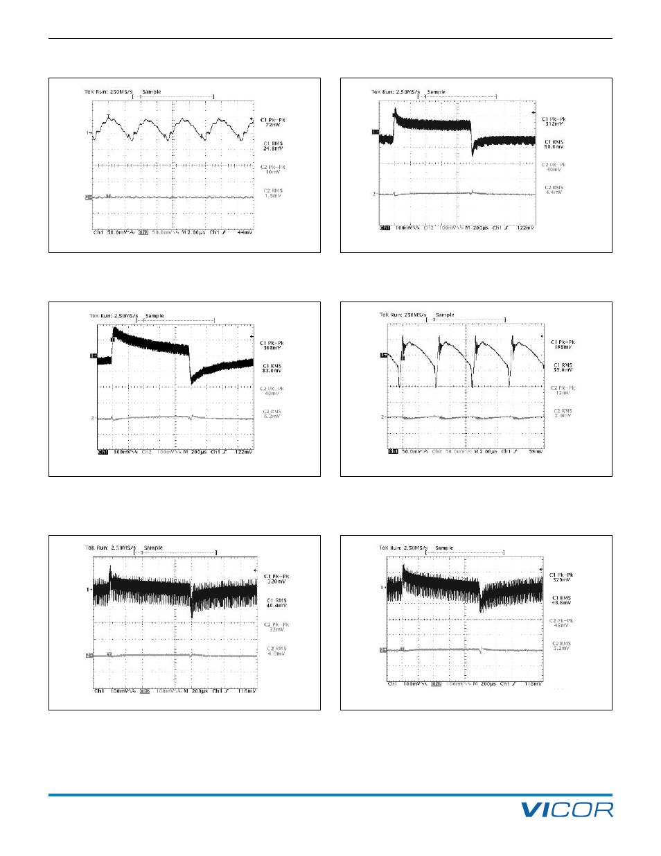
12. Output Ripple Attenuator Module (MicroRAM)
Figure 12–11 —
V375B12C250B and µRAM; Input and output ripple
@50% (10 A) load CH1 = Vi; CH2 = Vo; Vi – Vo = 305 mV; R
HR
= 80 k
(Configured as in Figures 14–1a and 14–1b)
Figure 12–8 — V375A28C600B and µRAM: Input and output
ripple @ 50% (10 A) load CH1 = Vi; CH2 = Vo; Vi – Vo = 332 mV;
R
HR
= 178 k
Figure 12–9 — V375A28C600B and µRAM; Input and output dynamic
response no added C
TRAN
; 20% of 20 A rating load step of 4 A
(10 A – 14 A); R
HR
= 178 k (Configured as in Figures 14–1a and 14–1b)
Figure 12–10 — V375A28C600B and µRAM; Input and output
dynamic response C
TRAN
= 820 µF Electrolytic; 33% of load step of
6.5 A (10 A–16.5 A); R
HR
= 178 k (Configured as in Figures 14–1a
and 14–1b)
Figure 12–13 — V300B12C250B and µRAM; Input and output
dynamic response C
TRAN
= 820 µF Electrolytic; 30% of load step
of 6 A (10 A – 16 A); R
HR
= 80 k (Configured as in Figures
14–1a
and 14–1b
)
Figure 12–12 — V300B12C250B and µRAM; Input and output
dynamic response no added C
TRAN
; 18% of 20 A rating load step of
3.5 A (10 A – 13.5 A); R
HR
= 80 k (Configured as in Figures
14–1a
and 14–1b
)