Control pin functions and applications – Vicor Micro Family of DC-DC Converter User Manual
Page 11
Design Guide & Applications Manual
For Maxi, Mini, Micro Family DC-DC Converters and Configurable Power Supplies
Maxi, Mini, Micro Design Guide
Rev 4.9
vicorpower.com
Page 10 of 88
Apps. Eng. 800 927.9474
800 735.6200
2. Control Pin Functions and Applications
+OUT
+S
SC
–S
–OUT
R
U
Trim Up
Load
Error
Amp
1 k
Ω
1.23 V
0.033
μF
1,000 (Vout –1.23) Vnom
1.23 (Vout – Vnom)
R
U
(ohms) =
– 1,000
R
U
Trim Up
Load
Error
Amp
1 kΩ
1.23 V
0.033 µF
+OUT
SC
–OUT
+IN
PC
PR
–IN
1,000 (Vout –1.23) Vnom
1.23 (Vout – Vnom)
R
U
(ohms) =
– 1,000
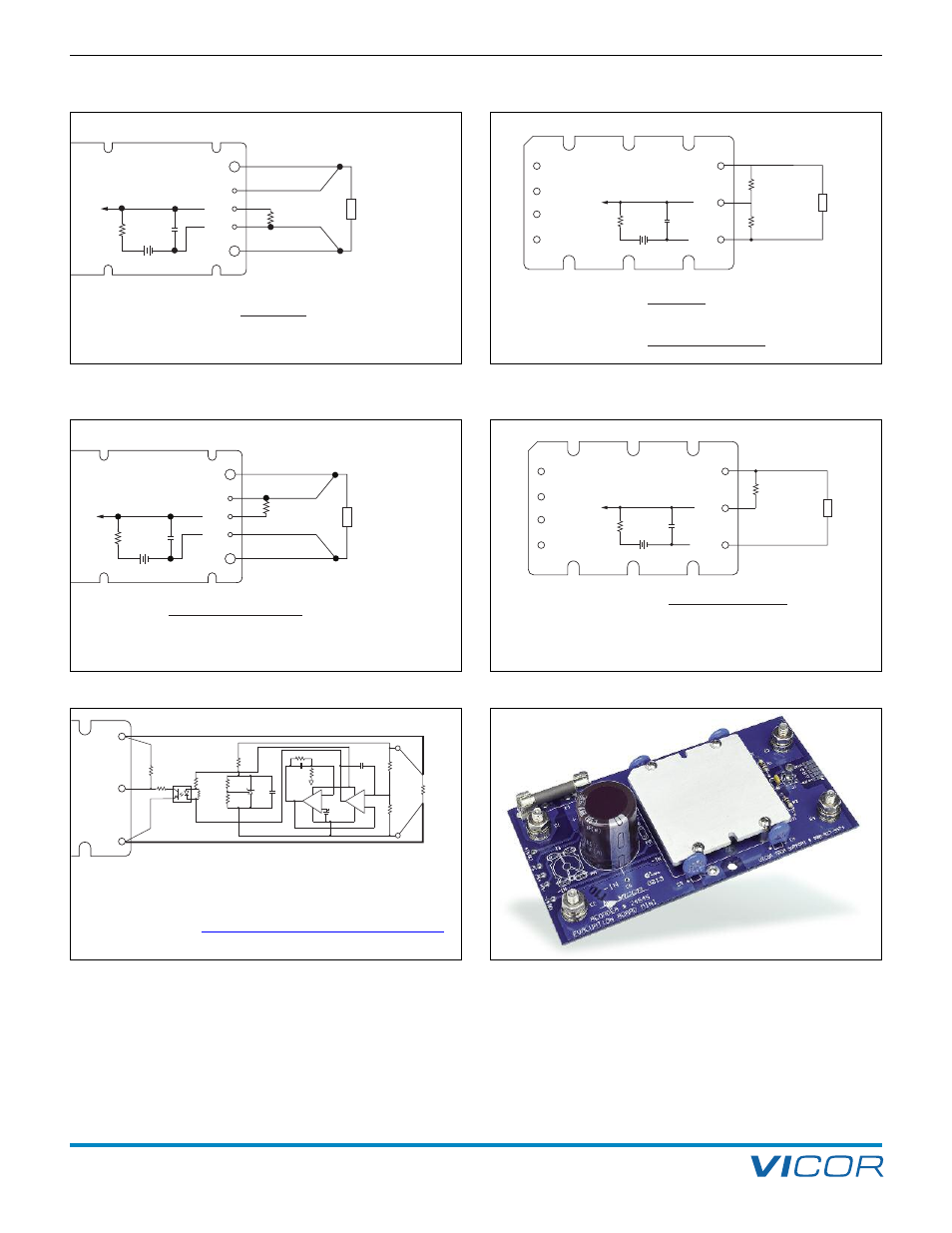
Figure 2–13a — Output voltage trim up circuit (Maxi / Mini)
Figure 2–13b — Output voltage trim up circuit (Micro)
+ +
– –
+ +
– –
R1
R2
U1
R3
2.55 k
R4
R5
1.00 k
U2
TLV431
C1
R7 21.0 k
C2
0.22 µF
R8
4.02 k
C3
R9
R10
1.24 k
U3
LM10
+S
–S
+Out
SC
–Out
R Load
PS2701
R11
36.5 k
R6
1.65 k 470 pF
200 mV
Vcc
Gnd
Figure 2–14 — Voltage drop compensation (Micro).
Figure 2–15 — Evaluation Boards; Available for Maxi, Mini and Micro
Family DC-DC converters
• This module is designed for point of load regulation, where remote sensing
is not required. Active voltage drop compensator, as shown here, may be
used in applications with significant distribution losses.
Please consult with the
for additional information.
Load
+OUT
+S
SC
–S
–OUT
R
D
Trim Down
Error
Amp
1 k
Ω
1.23 V
0.033
μF
1,000 Vout
Vnom – Vout
R
D
(ohms) =
Load
R
D
Trim Down
Error
Amp
1 k
Ω
1.23 V
0.033
μF
+OUT
SC
–OUT
+IN
PC
PR
–IN
1,000 Vout
Vnom – Vout
R
D
(ohms) =
1,000 (Vout –1.23) Vnom
1.23 (Vout – Vnom)
R
U
(ohms) =
– 1,000
R
U
Trim Up
Figure 2–12a — Output voltage trim down circuit (Maxi / Mini)
Figure 2–12b — Output voltage trim down circuit (Micro)