Modular ac front-end system (enmod)s – Vicor Micro Family of DC-DC Converter User Manual
Page 47
Design Guide & Applications Manual
For Maxi, Mini, Micro Family DC-DC Converters and Configurable Power Supplies
Maxi, Mini, Micro Design Guide
Rev 4.9
vicorpower.com
Page 46 of 88
Apps. Eng. 800 927.9474
800 735.6200
9. Modular AC Front-end System (ENMod)s
The approximate conduction angle is given by:
θ = cos
-1
(V
2
/ V
1
)
(5)
Another consideration in hold-up capacitor selection is
their ripple current rating. The capacitors’ rating must be
higher than the maximum operating ripple current. The
approximate operating ripple current (rms) is given by:
I
rms
= 2P / Vac
(6)
where: P = total output power
V
ac
= operating line voltage
Calculated values of bus capacitance for various hold-up
time, ride-through time, and ripple voltage requirements
are given as a function of operating power level in Figures
9–14, 9–15, and 9–16, respectively.
EXAMPLE
In this example, the output required from the DC-DC
converter at the point of load is 12 Vdc at 320 W.
Therefore the output power from the ENMods would be
375 W (assuming a converter efficiency of 85%). The
desired hold-up time is 9 ms over an input range of
90 to 264 Vac.
Determining Required Capacitance for Power Fail
Warning. Figure 9–14 is used to determine capacitance
for a given power fail warning time and power level, and
shows that the total bus capacitance should be at least
820 µF. Since two capacitors are configured in series, each
capacitor should be at least 1,640 µF. Note that warning
time is not dependent on line voltage.
A hold-up capacitor calculator is available on the Vicor
website, at
Determining Ride-through Time. Figure 9–15 illus-
trates ride-through time as a function of line voltage
and output power, and shows that at a nominal line of
90 Vac, ride-through would be 68 ms. Ride-through
time is a function of line voltage.
Determining Ripple Voltage on the Hold-up
Capacitors. Figure 9–16 is used to determine ripple
voltage as a function of operating power and bus
capacitance, and shows that the ripple voltage across
the hold-up capacitors will be 12 Vp-p.
Determining the Ripple on the Output of the
DC-DC Converter. Figure 9–17 is used to determine
the ripple rejection of the DC-DC converter and indicates
a ripple rejection of approximately 60 dB for a 12 V
output. Since the ripple on the bus voltage is 12 Vac
and the ripple rejection of the converter is 60 dB, the
output ripple of the converter due to ripple on its input
(primarily 120 Hz) will be 12 m Vp-p.
A variety of hold-up capacitor options are available.
Please visit our website at
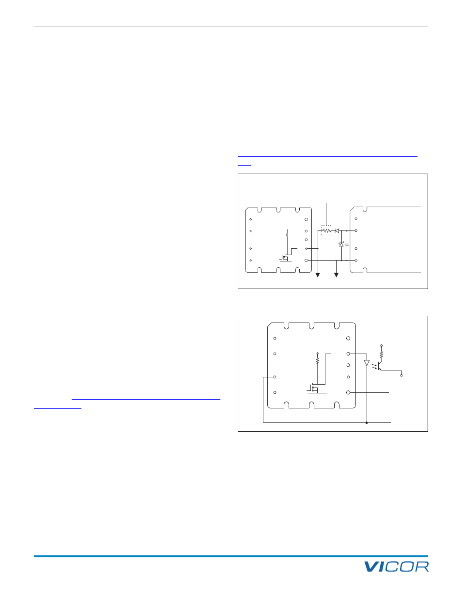
+IN
PC (GATE IN)
PR
–IN
N
EMI GND
SR
L
+
EN
–
150 k
15 Vdc
Micro-
controller
Vicor DC-DC
Converter
FARM3
BOK
ST
Not used with VI-260/VI-J60
Figure 9–11 — Enable (EN) function
N
EMI GND
SR
L
+
BOK
ST
EN
–
Micro-
controller
15 Vdc
27 k
Ω
+5 Vdc
Secondary
referenced
FARM3
Figure 9–12 — Bus OK (BOK) isolated power status indicator