High boost ham, Figure 10–10 — recommended ham filter, Figure 10–8 — enable output (e/o) – Vicor Micro Family of DC-DC Converter User Manual
Page 52: Figure 10–9 — start-up / shut-down timing diagram, Table 10-1 — ham filter inductance range
Design Guide & Applications Manual
For Maxi, Mini, Micro Family DC-DC Converters and Configurable Power Supplies
Maxi, Mini, Micro Design Guide
Rev 4.9
vicorpower.com
Page 51 of 88
Apps. Eng. 800 927.9474
800 735.6200
L
IN
E
L
O
A
D
R
Cx
Cy
Cy
D1
D2
D3
HAM Filter P/N 30205
R = 235 K
Ω D1,2 = 1.5KE130CA D3 = 1.5KE150CA
MOV
*
P/N 30076
Cx = 1.5 uF(x2)SH Cy = 0.01 uF, Y2 type LC = 6.9 mH LD = 0.72 mH
*MOV required external to filter to meet normal mode transient surge requirements
CM
DM
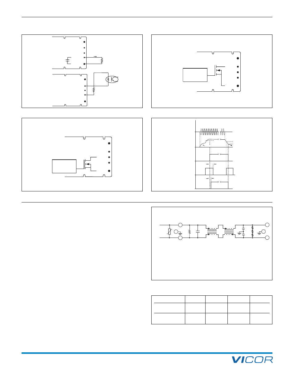
Figure 10–10 — Recommended HAM filter
10. High Boost HAM
+OUT
P/OK
–OUT
E/O
A/S
18 kΩ, 1/4 W
"Power OK" Status
Low = OK
LOGIC
P/OK
–OUT
+OUT
E/O
S
G
D
A/S
Figure 10–6 — Auxiliary Supply (A/S)
Figure 10–7 — Power OK (P/OK)
LOGIC
E/O
–OUT
+OUT
P/OK
A/S
S
G
D
Figure 10–8 — Enable Output (E/O)
Outputs
DC-DC Converter(s)
Rectified Line
Enable Output (E/O)
DC Output
of HAM
Power OK (P/OK)
AC Mains
120 Vrms
Boost Voltage
250 Vdc
280 Vdc
Off at 250 Vdc
Off at 270 Vdc
270 Vdc
25 ms
10 ms
Off below 250 Vdc
Figure 10–9 — Start-up / shut-down timing diagram
A/S
E/O
P/OK
+OUT
–OUT
IAS ≤ 3 mA
19 – 23 V
+
–
DO NOT OVERLOAD
or directly connect a capacitor
to the A/S terminal.
A line filter is required to provide attenuation of
conducted emissions generated by the HAM module and
to protect it from line transients. It also presents a well
defined high frequency AC line impedance to the input of
the HAM. To meet the listed specifications, Vicor’s P/N
30205 line filter/transient suppressor or equivalent must
be used, see Figure 10–10. The addition of a MOV
external to this filter is required to meet normal mode
transient surge requirements.
For applications using HAMD + BAMD or where the user
desires to construct a custom HAM filter, the filter should
be designed following Figure 10–10, the schematic of
Vicor’s P/N 30205 filter. The current carrying capability of
the inductors must be scaled proportionally to the number
of HAM modules used. Inductance values must be
selected according to Table 10–1. These limits are to
ensure proper operation of the HAM and do not
guarantee a system will meet conducted emissions specifi-
cations.
For applications requiring magnetic field shielding, do not
place a ferrous EMI shield over the plastic cover of the
HAM module. This can cause thermal problems due to
induction heating effects.
LINE FILTER FOR HIGH BOOST HAM
Parameter
Min
Typ
Max
Unit
Differential Mode
0.2
0.35
0.75
mH
Inductance (LD)
Common Mode
3
6
mH
Inductance (LC)
Table 10-1 — HAM filter inductance range