Autoranging rectifier module (arm), Π– θ θ – Vicor Micro Family of DC-DC Converter User Manual
Page 35
Design Guide & Applications Manual
For Maxi, Mini, Micro Family DC-DC Converters and Configurable Power Supplies
Maxi, Mini, Micro Design Guide
Rev 4.9
vicorpower.com
Page 34 of 88
Apps. Eng. 800 927.9474
800 735.6200
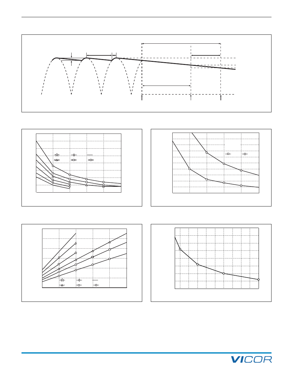
7. Autoranging Rectifier Module (ARM)
Figure 7–10 — Ripple voltage vs. operating power and bus
capacitance, series combination of C1, C2 (Figure 7–3)
Figure 7–11 — Converter ripple rejection vs. output voltage (Typical)
Operating Power (W)
P
-P
R
ip
p
le
V
o
lt
a
g
e
(
V
a
c
)
0
5
10
15
20
25
30
1500
1250
1000
750
500
250
*
*
2,200 µF
1,600 µF
1,300 µF
*
1,100 µF
820 µF
680 µF (VI-ARM-x1)
(VI-ARMB-x2)
Output Voltage
R
ip
p
le
R
e
je
c
ti
o
n
(
d
B
)
40
45
50
55
60
65
70
75
80
50
30
15
5
2
Operating Power (W)
R
id
e
–
T
h
ro
u
g
h
T
im
e
(
m
s
)
0
10
20
30
40
50
60
70
80
90
100
90 Vac
115 Vac
1500
1250
1000
750
500
250
Total
capacitance
820
µF
Figure 7–9 — Ride-through time vs. operating power
Figure 7–7 — General timing diagram of bus voltage following interruption of the AC mains
205 V
190 V
Power Fail
Power Fail
Warning
Bus OK
Converter
Shut down
Hold-up Time
254 V
Ride-Through Time
Ripple (V p-p)
π
– θ
θ
Figure 7–8 — Power fail warning time vs. operating power and
total bus capacitance, series combination of C1, C2 (Figure 7–3)
Operating Power (W)
P
o
w
e
r
F
a
il
W
a
rn
in
g
T
im
e
(
m
s
)
0
5
10
15
20
25
30
35
40
1500
1250
1000
750
500
250
*
*
2,200 µF
1,600 µF
1,300 µF
*
1,100 µF
820 µF
680 µF (VI-ARM-x1)
(VI-ARMB-x2)