Control pin functions and applications, Primary control (pc pin), Disable disable = pc <2.3 v – Vicor Micro Family of DC-DC Converter User Manual
Page 6: Out sc –out +in pc pr –in
Design Guide & Applications Manual
For Maxi, Mini, Micro Family DC-DC Converters and Configurable Power Supplies
Maxi, Mini, Micro Design Guide
Rev 4.9
vicorpower.com
Page 5 of 88
Apps. Eng. 800 927.9474
800 735.6200
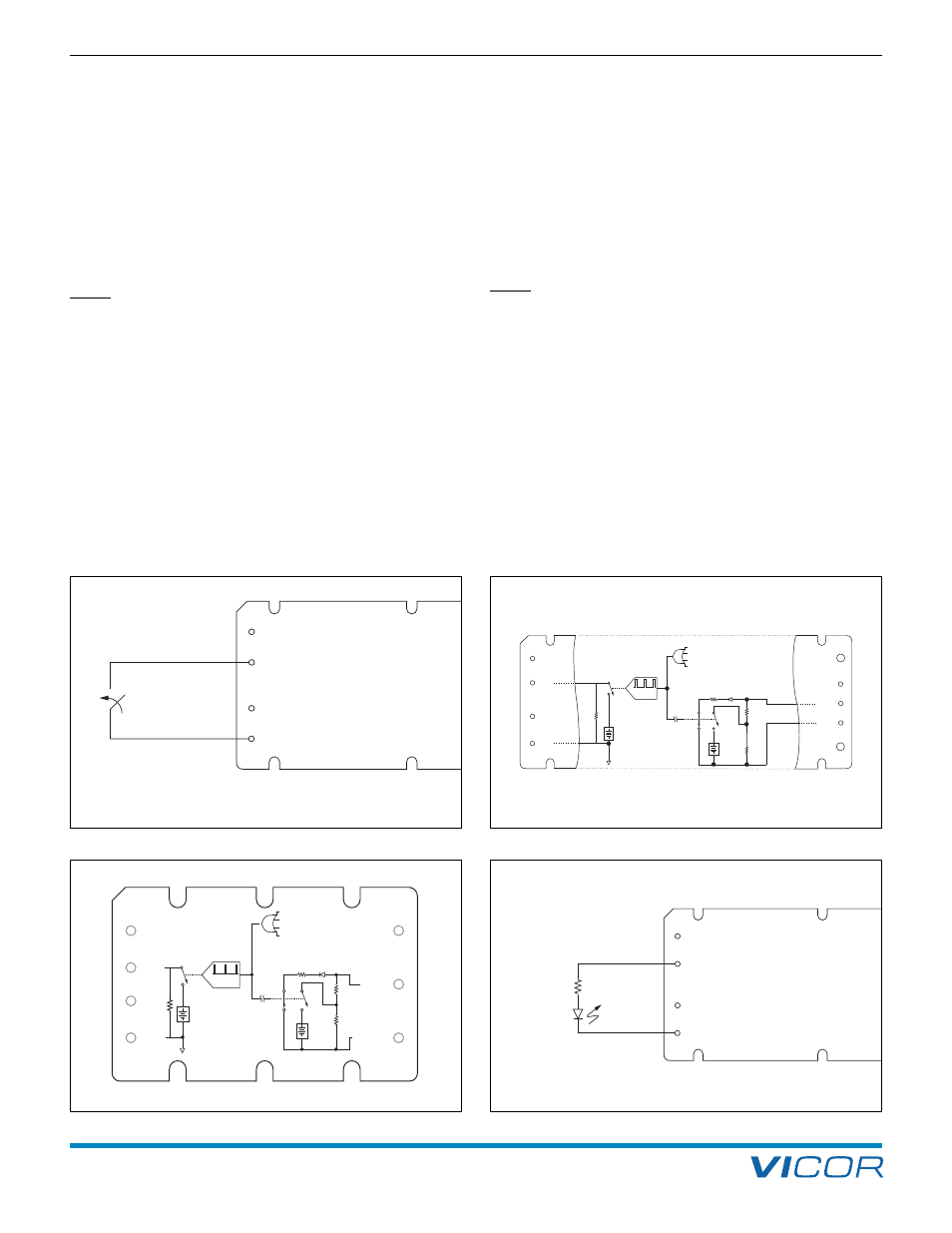
2. Control Pin Functions and Applications
+IN
PC
PR
–IN
4 k
Ω
"Module
Enabled"
Module Enable / Disable. The module can be disabled
by pulling the PC below 2.3 V with respect to the –Input.
This should be done with an open-collector transistor,
relay, or optocoupler. Multiple converters may be disabled
with a single transistor or relay via “ORing” diodes. When
using a mechanical switch or relay to control the PC pin,
please ensure that the contacts are properly debounced
with a capacitor (10 nF max.) to avoid switch bounce.
NOTE: Do not exceed a repetitive on / off rate of
1 Hz to the PC pin or input voltage pins.
An optocoupler must be used when converters are located
on different PC boards, when a common-mode inductor
is used directly at the module input, or when the distance
between the converters would cause excessive voltage
drops. Under no circumstances should the PC pin be
pulled negative more than a diode drop below the module
–IN. (Figure 2–1) When the PC pin is pulled low the PC
current will pulse similar to the PC voltage shown in
Figure 2–4. When the outputs of two or more converters
are connected in a parallel array to increase system power
the converters should be “group enabled” to ensure that
all the converters start at the same time. The PC pins of all
converters in the array should be controlled by an external
circuit which will enable the converters once the input
voltage is within the normal operating range.
Primary Auxiliary Supply. At 5.75 V, the PC can source
up to 1.5 mA. In the example shown in Figure 2–3, PC
powers a LED to indicate the module is enabled.
Another example of an isolated on-state indicator is
shown in Figure 2–5.
NOTE: When the module has detected a fault or
when the input voltage is above or below the
normal operating range the PC voltage will pulse.
Module Alarm. The module contains “watchdog” circuitry
that monitors input voltage, operating temperature, and
internal operating parameters. (Figures 2–2a and 2–2b) If
any of these parameters is outside their allowable
operating range, the module will shut down and PC will
go low. (Figure 2–4) Then PC will periodically go high and
the module will check to see if the fault (as an example,
input undervoltage) has cleared. If the fault has not been
cleared, PC will go low again and the cycle will restart.
The SC pin will go low when a fault occurs and return to
its normal state after the fault has been cleared. An example
of using a comparator for monitoring on the secondary is
shown in Figures 2–6a and 2–6b.
Figure 2–3 — LED on-state indicator
Figure 2–2a — PC and SC module alarm logic (Maxi / Mini)
+IN
PC
PR
–IN
Disable
Disable = PC <2.3 V
+OUT
+S
SC
–S
– OUT
+IN
PC
PR
–IN
Input Undervoltage
2-20 ms typ.
f (VIN)
Auto
Restart
5.7 Vdc
(0-3 mA)
50
Ω
SW2
SW3
1.23
Vdc
6 K
1 K
SW1
SW1, 2, & 3
shown in
"Fault" position
Input Overvoltage
(See Note 1)
Overtemperature
Module Faults
1
Not applicable for 300 Vdc input family
1 M
Input Undervoltage
Input Overvoltage
[a]
Over Temperature
Module Faults
2-20 ms typ.
f(V
IN
)
Auto
Restart
5.7 Vdc
(0-3 mA)
50
Ω
SW2
SW3
1.23
Vdc
6 K
1 K
SW1
SW1, 2, & 3 shown
in "Fault" position
+OUT
SC
–OUT
+IN
PC
PR
–IN
[a]
Not applicable for 300 Vdc Input family
1 M
PRIMARY CONTROL (PC PIN)
Figure 2–1 — Module Enable / Disable
Figure 2–2b — PC and SC module alarm logic (Micro)