Output ripple attenuator module (microram) – Vicor Micro Family of DC-DC Converter User Manual
Page 62
Design Guide & Applications Manual
For Maxi, Mini, Micro Family DC-DC Converters and Configurable Power Supplies
Maxi, Mini, Micro Design Guide
Rev 4.9
vicorpower.com
Page 61 of 88
Apps. Eng. 800 927.9474
800 735.6200
12. Output Ripple Attenuator Module (MicroRAM)
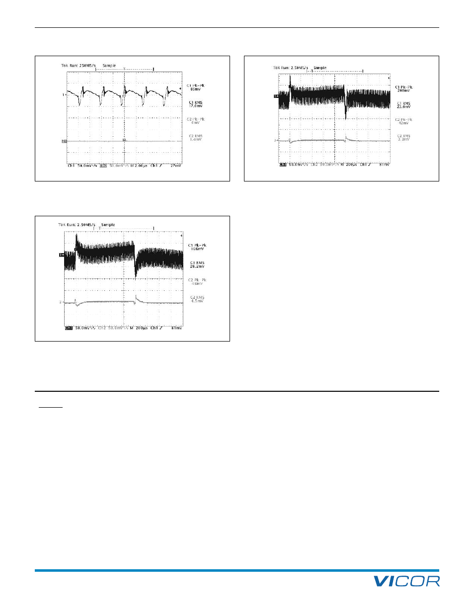
Figure 12–15 — V48C5C100B and µRAM; Input and output
dynamic response no added C
TRAN
; 23% of 20 A rating load step
of 4.5 A (10 A – 14.5 A); R
HR
= 31 k (Configured as in Figures
12–1a
and 12–1b
)
Figure 12–16 — V48C5C100B and µRAM; Input and output
dynamic response C
TRAN
= 820 µF Electrolytic; 35% of load step
of 7 A (10 A – 17 A); R
HR
= 31 k (Configured as in Figures
12–1a
and 12–1b
)
Figure 12–14 — V48C5C100B and µRAM; Input and output ripple
@ 50% (10 A) load CH1 = Vi; CH2 = Vo; Vi – Vo = 327 mV;
R
HR
= 31 k (Configured as in Figures
12–1a and 12–1b
)
NOTES: The measurements in Figures 12–8 through 12–16 were taken with a µRAM2C21 and standard scope probes
set at 20 MHz bandwidth scope setting.
The criteria for transient current capability was as follows: The transient load current step was incremented
from 10 A to the peak value indicated, then stepped back to 10 A until the resulting output peak to peak
measured ~ 40 mV.