Design requirements, Onboard mount, Inboard mount – Vicor Micro Family of DC-DC Converter User Manual
Page 18: Exploded view, Out +in –in –out maxi, mini, micro dc-dc converter
Design Guide & Applications Manual
For Maxi, Mini, Micro Family DC-DC Converters and Configurable Power Supplies
Maxi, Mini, Micro Design Guide
Rev 4.9
vicorpower.com
Page 17 of 88
Apps. Eng. 800 927.9474
800 735.6200
3. Design Requirements
0.53
Chassis
0.46
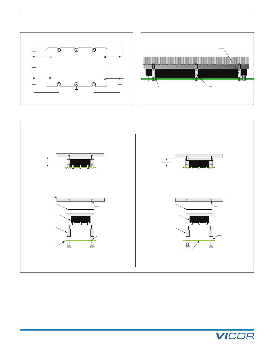
Onboard Mount
Cross-sectional view of pins
and mounting hardware
Inboard Mount
Cross-sectional view of pins
and mounting hardware.
Exploded View
Exploded View
P/N 20265 Ther mMate
Ex. V300C12M75BL
(Long Solder Pin,
Slotted Baseplate)
P/N 18157 Standoff Kit
PCB thickness is
0.062
" (
1.5mm)
Tapped #4–40
screw hole
Pad and plated through-
hole connected to
chassis ground plane
P/N 20265 Ther mMate
Ex. V300C12M75B
(Shor t Solder Pin,
Slotted Baseplate)
P/N 18151 Standoff Kit
0.062
" (1.5mm) PCB with
aperture to allow belly
of
the module to recess into board
Tapped #4–40
screw hole
Pad and plated through-
hole connected to
chassis ground plane
13,5mm
11,7 mm
’’
’’
Figure 3–4 — Onboard vs. inboard mounting of (1/4 brick) Micro with slotted baseplate
+OUT
+IN
–IN
–OUT
Maxi, Mini, Micro
DC-DC Converter
C1a
C1b
C2a
C2b
C
IN
Baseplate grounded
Figure 3–2 — Minimum recommended bypassing for Maxi, Mini,
and Micro; Keep all leads short.
Standoffs also provide necessary
mechanical support in order to
prevent mechanical stresses from
damaging the module during shock / vibration.
Standoff sitting on pad / plated through-hole
that is connected to the chassis
ground plane within the PCB.
Female-female standoffs are
shown, however standoffs are
also available in male-female versions.
Figure 3–3 — Recommended mounting method using standoffs