High density dc-dc converter technology – Vicor Micro Family of DC-DC Converter User Manual
Page 5
Design Guide & Applications Manual
For Maxi, Mini, Micro Family DC-DC Converters and Configurable Power Supplies
Maxi, Mini, Micro Design Guide
Rev 4.9
vicorpower.com
Page 4 of 88
Apps. Eng. 800 927.9474
800 735.6200
1. High Density DC-DC Converter Technology
+ OUT
+ SENSE*
SC
– OUT
– SENSE*
+ IN
PC
PR
– IN
Primary Control IC
Secondary Control IC
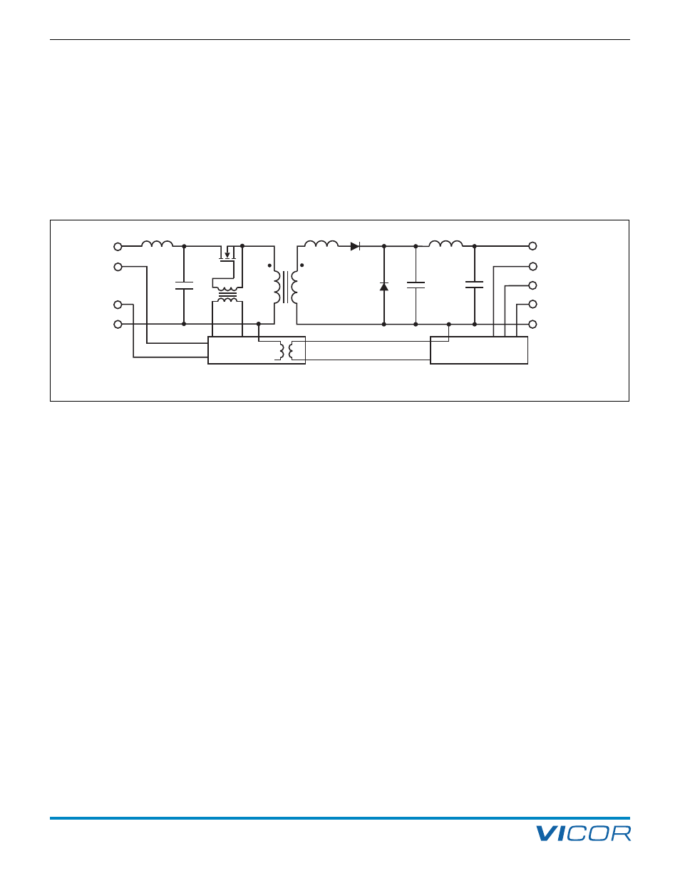
The Maxi, Mini, Micro’s ZCS / ZVS power-processing
architecture (Figure 1–3) enables efficient, low-noise,
high-frequency operation. The main switch is common
drain for improved thermal and noise management,
the reset switch located within the primary control IC
is common source for ease of control.
The control circuitry is integrated into two (primary and
secondary side) ICs. The result is a significant reduction in
parts with the ensuing savings in cost and increase in
reliability. This integration also provides extra room for
the power train.
Maxi, Mini, Micro transformers place the primary and
secondary windings far apart, but contain the magnetic
flux using a copper armor plated onto the ferrite core.
The armor also conducts excess heat to the baseplate.
Figure 1–3 — Maxi, Mini, Micro: Basic power train and control (*Not included in Micro family)