Output ripple attenuator module (microram), Capacitance to the c, Capacitance to the v – Vicor Micro Family of DC-DC Converter User Manual
Page 57: Functional description
Design Guide & Applications Manual
For Maxi, Mini, Micro Family DC-DC Converters and Configurable Power Supplies
Maxi, Mini, Micro Design Guide
Rev 4.9
vicorpower.com
Page 56 of 88
Apps. Eng. 800 927.9474
800 735.6200
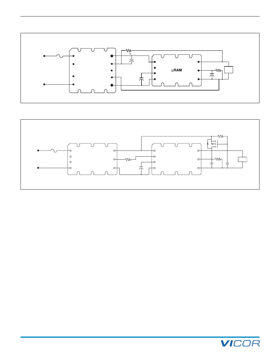
12. Output Ripple Attenuator Module (MicroRAM)
The MicroRAM has an internal passive filter, (Figure 12–2)
that effectively attenuates ripple in the 50 kHz to 1 MHz
range. An active filter provides attenuation from low
frequency up to the 1 MHz range. The user must set the
headroom voltage of the active block with the external
R
HR
resistor to optimize performance. The MicroRAM
must be connected as shown in Figures 12–1a or 12–1b
depending on the load-sensing method. The transient
load current performance can be increased by the addition
of optional C
TRAN
capacitance to the C
TRAN
pin. The low-
frequency ripple attenuation can be increased by addition
of optional C
HR
capacitance to the V
REF
pin as shown in
Figures 12–3a and 12–3b.
Transient load current is supplied by the internal C
TRAN
capacitance, plus optional external capacitance, during the
time it takes the converter loop to respond to the increase
in load. The MicroRAM’s active loop responds in roughly
one microsecond to output voltage perturbations. There
are limitations to the magnitude and the rate of change
of the transient current that the MicroRAM can sustain
while the converter responds. See Figures 12–8 through
12–16 for examples of dynamic performance. A larger
headroom voltage setting will provide increased transient
performance, ripple attenuation, and power dissipation
while reducing overall efficiency. (Figures 12–4a, 12–4b,
12–4c, and 12–4d)
The active loop senses the output current and reduces the
headroom voltage in a linear fashion to approximate
constant power dissipation of MicroRAM with increasing
loads. (Figures 12–7, 12–8 and 12–9) The headroom
setting can be reduced to decrease power dissipation
where the transient requirement is low and efficient ripple
attenuation is the primary performance concern.
The active dynamic headroom range is limited on the low
end by the initial headroom setting and the maximum
expected load. If the maximum load in the application is
10 A, for example, the 1 A headroom can be set
75 mV lower to conserve power and still have active
headroom at the maximum load current of 10 A. The
high end or maximum headroom range is limited by the
internal ORing diode function.
DC-DC
Converter
+OUT
Vref
–OUT
+IN
SC
C
TRAN
–IN
+OUT
+S
SC
–S
–OUT
+IN
PC
PR
–IN
R
SENSE
5.1
22
m F
C
TRAN
*
*
Optional Component
R
HR
C
HR
*
LOAD
Figure 12–1a — Typical configuration using remote sense
DC-DC
Converter
+OUT
SC
–OUT
+IN
PC
PR
–IN
μRAM
+OUT
Vref
–OUT
+IN
SC
C
TRAN
–IN
R
SC
R
HR
C
TRAN
*
C
HR
*
*
Optional Component
20 k
Ω
1 µF
IRML6401
LOAD
Figure 12–1b — Typical configuration using SC control (Optional C
HR
, 25 µF maximum in SC configuration.)
FUNCTIONAL DESCRIPTION