Control pin functions and applications – Vicor Micro Family of DC-DC Converter User Manual
Page 7
Design Guide & Applications Manual
For Maxi, Mini, Micro Family DC-DC Converters and Configurable Power Supplies
Maxi, Mini, Micro Design Guide
Rev 4.9
vicorpower.com
Page 6 of 88
Apps. Eng. 800 927.9474
800 735.6200
2. Control Pin Functions and Applications
A unique feature has been designed into Vicor Maxi, Mini,
Micro converter modules that facilitates parallel operation
for power expansion or redundancy. The PR pin is a bi-
directional port that transmits and receives information
between modules. The pulse signal on the parallel (PR)
bus serves to synchronize the high-frequency switching of
each converter which in turn forces them to load share.
These modules possess the ability to arbitrate the leader-
ship role; i.e., a democratic array. The module that
assumes command transmits the sync pulse on the parallel
bus while all other modules on the bus listen. In the event
of a failure of the lead module, the array “elects” a new
leader with no interruption of the output power.
Connection methods for the PR bus include:
1. AC-coupled single-wire interface: All PR pins are
connected to a single communication bus through
0.001 µF (500 V) capacitors. This interface supports
current sharing and is fault tolerant except for the
communication bus. (Figure 2–7) This method may
normally be used with a maximum of three converters.
2. Transformer-coupled interface: Modules or arrays of
modules may also be interfaced to share a load while
providing galvanic isolation between PR pins via a
transformer-coupled interface. For large arrays,
buffering may be required. The power source for the
buffer circuit may be derived from the PC pins. For
arrays of four or more modules, the transformer
coupled interface is recommended. (Figure 2–8)
+IN
PC
PR
–IN
Optocoupler
4 k
Ω
Alarm
1.00V
+OUT
+S
SC
–S
–OUT
Comparator
Alarm
1.00 V
+OUT
SC
–OUT
+IN
PC
PR
–IN
Comparator
2–20 ms typ.
Fault
SC
PC
1.23 V
5.7 V
40
μs typ.
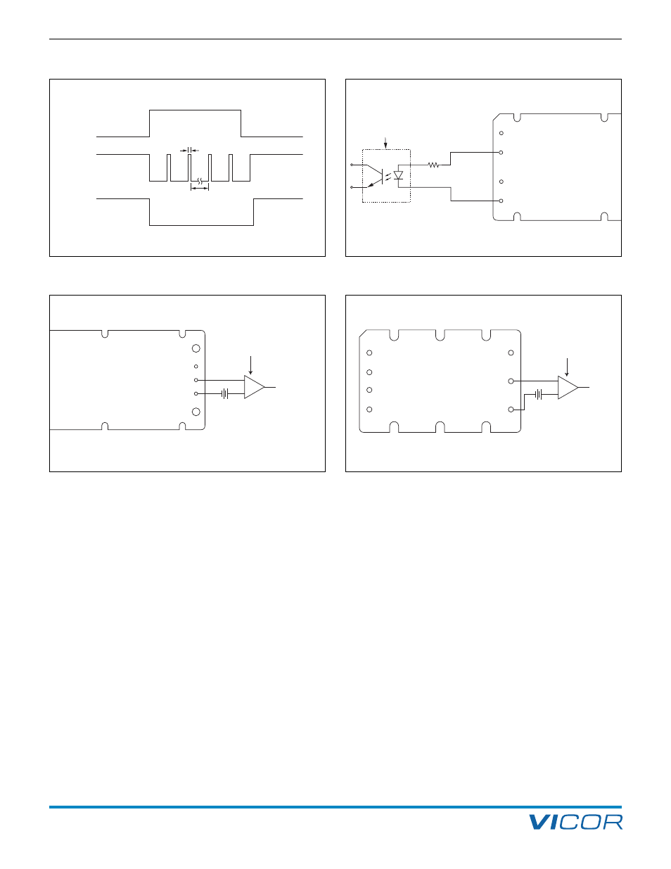
Figure 2–4 — PC / SC module alarm timing
Figure 2–5 — Isolated on-state indicator
Figure 2–6a — Secondary side on-state (Maxi / Mini)
Figure 2–6b — Secondary side on-state (Micro)
PARALLEL BUS (PR PIN)