High boost ham – Vicor Micro Family of DC-DC Converter User Manual
Page 49
Design Guide & Applications Manual
For Maxi, Mini, Micro Family DC-DC Converters and Configurable Power Supplies
Maxi, Mini, Micro Design Guide
Rev 4.9
vicorpower.com
Page 48 of 88
Apps. Eng. 800 927.9474
800 735.6200
10. High Boost HAM
THE HIGH-BOOST HARMONIC ATTENUATOR
MODULE COMPATIBLE WITH V375, VI-26x
AND VI-J6x FAMILIES
The High-Boost Harmonic Attenuation Module (HAM)
consists of a full-wave rectifier, a high-frequency zero-
current-switching (ZCS) boost converter, active inrush
current limiting, short-circuit protection, control, and
housekeeping circuitry (Figure 10–1). The incoming
AC line is rectified and fed to the boost converter. The
control circuitry varies the operating frequency of the
boost converter to regulate and maintain the output
voltage of the HAM above the peak of the incoming
line, while forcing the input current to follow the
waveshape and phase of the line voltage. A power
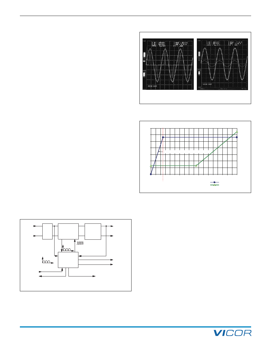
factor better than 0.99 is achieved (Figure 10–2).
Operating efficiency of the boost converter is optimized
at any incoming line voltage by an adaptive output
voltage control scheme.
The output voltage of the HAM is a function of incoming
AC line voltage (Figure 10–3). On a nominal 115 Vac line,
the output voltage of the HAM is 280 Vdc — well within
the input operating voltage range of Vicor V375 DC-DC
converters. Above 180 V input, the output voltage linearly
increases with input voltage. At 230 Vac the delivered
voltage will be approximately 365 V. For any given input
line voltage, the HAM maintains enough headroom
between the output voltage and peak input voltage to
ensure high quality active power factor correction without
sacrificing operating efficiency.
The HAMD version does not contain an internal bridge
rectifier and is intended for configuring higher power arrays
with Booster versions, referred to as the VI-BAMD
(Figure 10–5).
L1 and L2/N (HAM) Pin. An appropriate line filter is
required to limit conducted emissions and ensure reliable
operation of the HAM, see page 51. Connect single phase
AC mains to the input of the line filter via a 10 A, 250 V
fuse. Connect the output of the filter to L1 and L2/N of
the HAM. Do not put an X-capacitor across the input of
the HAM or use a line filter with an X-capacitor on its
output as power factor correction may be impacted.
+IN, –IN (HAMD, BAMD) Pin. These pins are connected
to the output of the external bridge rectifier in HAMD /
BAMD configurations (Figure 10–5).
GATE IN (HAM) Pin. The user should not make any
connection to this pin.
GATE IN (HAMD) Pin. This pin provides line voltage
envelope and phase information for power factor
correction. This connection must be made through the
synchronization diodes between the line filter and bridge
rectifier (Figure 10–5).
Note:
Non-Isolated
Output
Gate In
Gate Out
ZCS
Boost
Converter
Inrush
& Short
Circuit
Protection
High Frequency
Control
Voltage
Waveform
Current
Sense
AC
Line
Control
& House-
keeping
Circuitry
Output Voltage
Module Enable
Power OK
DC
Out
Recti-
fier
Aux. Supply
+
–
NOTE: No input to output isolation.
Figure 10–1 — HAM block diagram (HAMD version has the rectifier
block deleted.)
Input Voltage
V
RMS
Rated Output Power
Output Voltage
Ou
tp
ut
P
ow
er
(W
)
Ou
tp
ut
Vo
lta
ge
(V
dc
)
400
450
500
550
600
650
700
85
250
300
350
400
375
425
325
275
95 105 115 125 135 145 155 165 175 185 195 205 215 225 235 245 255 265
derate output power 11 W/V for Vin <110 Vac
110
Figure 10–3 — Output voltage and power rating vs. input voltage
Figure 10–2 — Input voltage and current wave forms, without and
with power factor correction.