MTS SWIFT 10 MC Sensor User Manual
Page 90
SWIFT 10 MC Sensors
90
Road Simulator
Installing the Transducer
H. While holding the slip ring wires against the channel in the axle spacer,
insert the axle sleeve through the slip ring and the axle spacer.
I.
Bend the slip ring wires 90° and into the slot on the end of the axle
spacer.
J.
Insert the 9-pin connectors into their respective connector bracket on
the side of the hub adapter.
Note the orientation of the dovetail on the Board 1 and Board 2
connectors as shown in the figure on
K. Secure each connector with two 2-56 UNC flat head screws.
Apply Locktite 222 Threadlocker to each screw and torque to 0.56
N•m (5 lbf•in).
9. Assemble the transducer as follows:
A. Hold the inner hub adapter with the slip ring/encoder against the
inboard (connector) side of the transducer (see the next figure).
Align the connectors on the hub adapter with the connectors on the
transducer. Push the hub adapter onto the transducer to fully engage the
connectors.
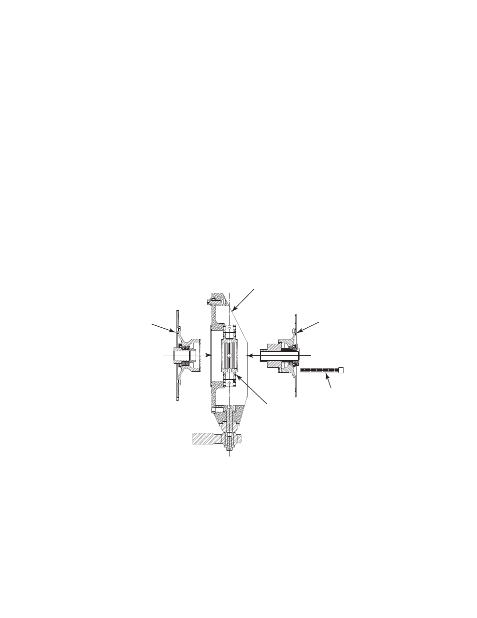
Typical Wheel Assembly (rear shown)
B. Hold the inner hub adapter without the slip ring/encoder against the
outboard side of the transducer.
Ensure the teeth in the hub adapter engage the teeth in the transducer.
Slip Ring/Encoder
Side Assembly
(rear shown)
Spindle Housing
(inboard side)
Transducer
(connector side)
Non-Slip Ring/Encoder
Side Assembly
(rear shown)
S10MC-35
M8 Fasteners (8)