MTS SWIFT 10 MC Sensor User Manual
Page 54
SWIFT 10 MC Sensors
54
Edit the Calibration File
Setting up the Transducer Interface
2. If necessary, edit the value for Polarity (see the table below).
The polarities that match the coordinate icon on the transducer are:
Fx=0
Fz=0
My=0
Using these settings, the axis orientation of the transducer relative to the
vehicle will vary depending on if the transducer output cable is on the right
side or left side of the vehicle.
The polarities for each axis can be reversed by changing the associates
polarity value from a “0” to a “1” or from a “1” to a “0”.
3. Perform this step for spinning application. For non-spinning applications,
skip to Step 4.
A. Verify the value for AngleMode.
Set the AngleMode=0
In this mode, the encoder pulses are summed in with the offset. At the
end of the process the value in the TI internal memory and is used to
perform the rotational transformation of the output signals.
B. The AngleOffset value is used when you are operating in encoder
mode (spinning applications). This value is summed with the encoder
output count. At the end of the process the value in the TI internal
memory and used when the angle mode is set to 0 (encoder). Negative
angles are converted to their positive equivalent so that the readback
value range is 0–360°.
The AngleOffset value is calculated by the TI during the zero process.
At the end of the process it is written to the calibration file.
There is no need to change this calculated value.
C. Verify that EncoderSize=2048.
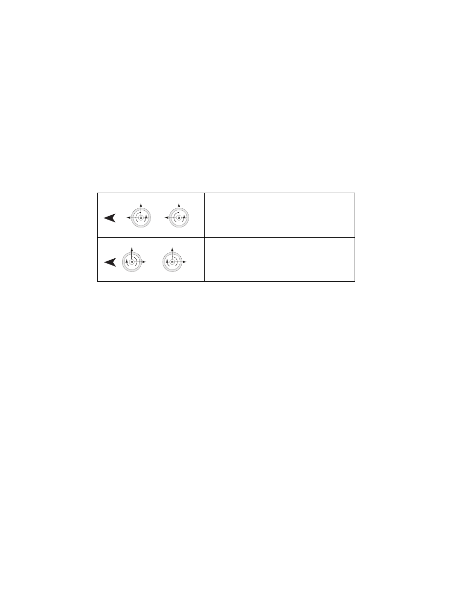
Example Transducer Orientation for Above Polarities
Matches the axis orientation on the front cover
of the SWIFT with output cable exiting the left
(near) side of vehicle.
Matches the axis orientation on the front cover
of the SWIFT with output cable exiting the right
(far) side of vehicle.
S10MC-23
Front
Fx
Fz
Fx
Fz
My
My
S10MC-36
Front
Fx
Fz
Fx
Fz
My
My