MTS SWIFT 10 MC Sensor User Manual
Page 68
SWIFT 10 MC Sensors
68
Road and Track Vehicles
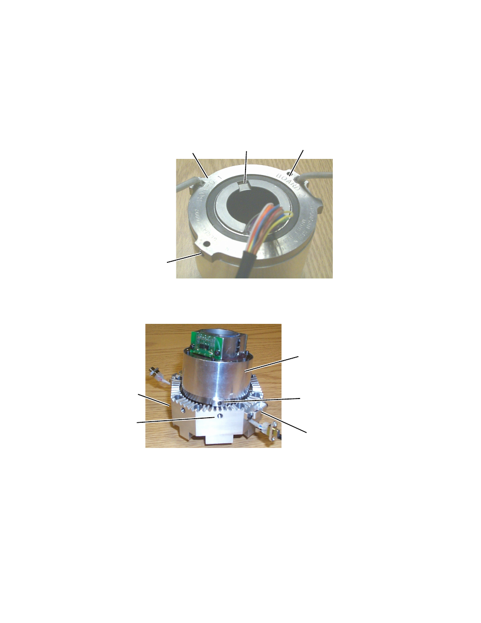
Installing the Transducer
D. Feed the slip ring wires for connection to the system cable assembly
through the inner hub assembly.
Note also at this time the Board 1 and Board 2 identifier stamped on the
face of the slip ring next to the 9-pin connector wires (see the next
figure). to facilitate assembly, mark each cable end to identify the cable
by board number.
E.
Orient the slip ring such that the pin hole for the setscrew is aligned
with the square head setscrew in the hub adapter.
F.
With the slip ring properly oriented, feed the 9-pin connectors and
cables through the closest hole in the side of the hub adapter.
G.
Fit the slip ring into the hub adapter. Rotate the slip ring and/or the axle
spacer as necessary, until the keyway in the slip ring engages the key in
the axle spacer.
Apply Locktite 262 Threadlocker to the square head setscrew and
tighten until fully seated.
H. While holding the slip ring wires against the channel in the axle spacer,
insert the axle sleeve through the slip ring and the axle spacer.
Board 2
Identifier
Board 1
Identifier
Keyway
Setscrew
Pin Hole
Hole for Square
Head Setscrew
Setscrew
Pin Hole
Transducer Cable
Connector Bracket (2)
Hub Adapter
Slip Ring