MTS SWIFT 10 MC Sensor User Manual
Page 66
SWIFT 10 MC Sensors
66
Road and Track Vehicles
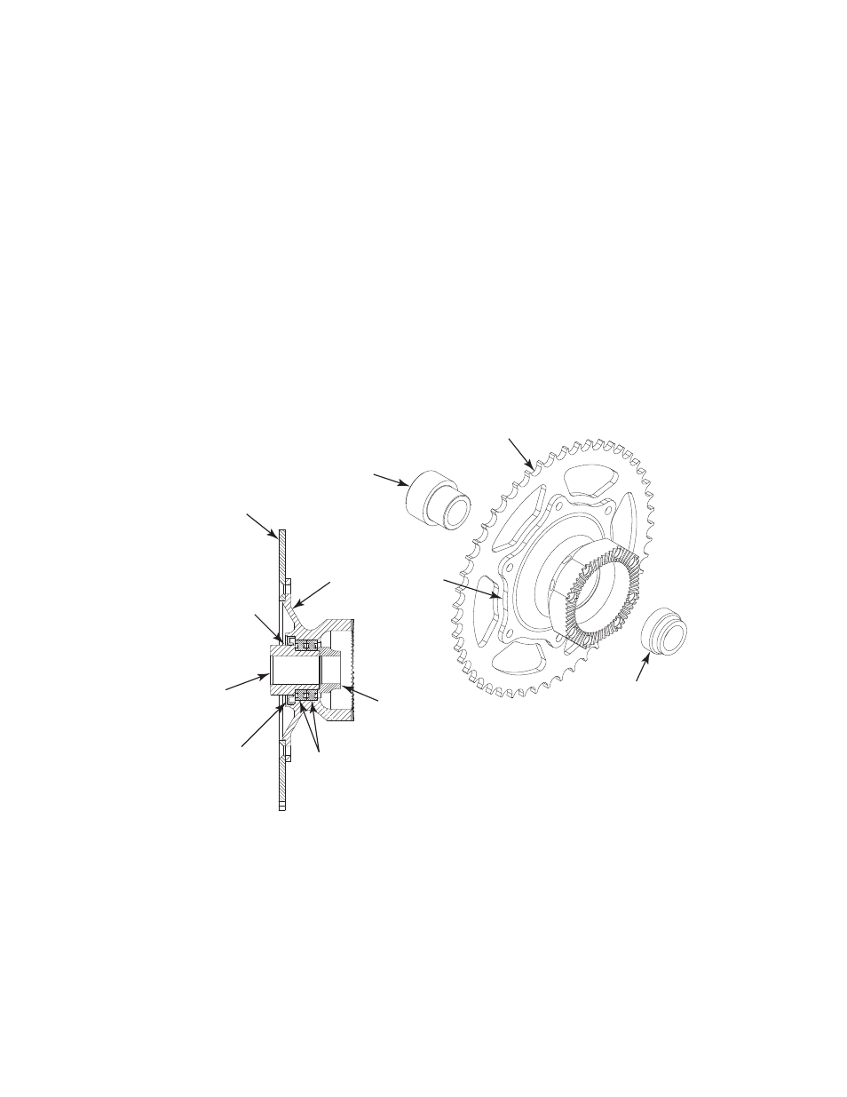
Installing the Transducer
7. Assemble the non-slip ring/encoder side as follows:
Note
The sealed bearings and oil seals shown in the figures have already
been installed in the delivered adapters.
A. If you have not already done so, attach the stock sprocket or brake disk
(as required) to the inner hub/sprocket or brake disk adapter using the
fasteners provided.
Apply Locktite 262 Threadblocker to the screws and torque to the
manufacturers specifications.
B. Apply a little grease or oil to the outer surface of the axle spacer and
insert it into the inner hub adapter from the sprocket or brake disk side.
Push until you feel it snap in place against the bearings.
C. Insert the load spacer from the opposite side.
D. Set this assembly aside.
Assembling the Non-Slip Ring/Encoder Side (typical – rear shown)
8. Assemble the slip ring/encoder side as follows:
A. If you have not already done so, attach the stock brake disk (if used) to
the inner hub/brake disk adapter using the fasteners provided.
Apply Locktite 262 Threadblocker to the screws and torque to the
manufacturers specifications.
Apply grease to reduce
friction between axle
spacer and oil seal
and bearings
Axle
Spacer
Axle
Spacer
Inner Hub/
Sprocket or
Brake Disk Adapter
Stock Sprocket (rear)
or Brake Disk (front)
Load Spacer
Load Spacer
Inner Hub Assembly
Sprocket Side – Rear (shown)
Stock Sprocket
or Brake Disk
Oil Seal
S10MC-12R
Sealed
Bearings (2)