MTS SWIFT 10 MC Sensor User Manual
Page 63
Road and Track Vehicles
SWIFT 10 MC Sensors
Installing the Transducer
63
A. Install a spoke hub adapter on each side of the transducer (see the next
figure).
Note
Keep in mind, when mounting the hub adapters to the transducer, the
path for routing the transducer cable. The transducer connectors should
on the side of the vehicle that will provide cable routing to the TI box that
will keep the cable away from moving parts, such as the sprocket and
drive chain.
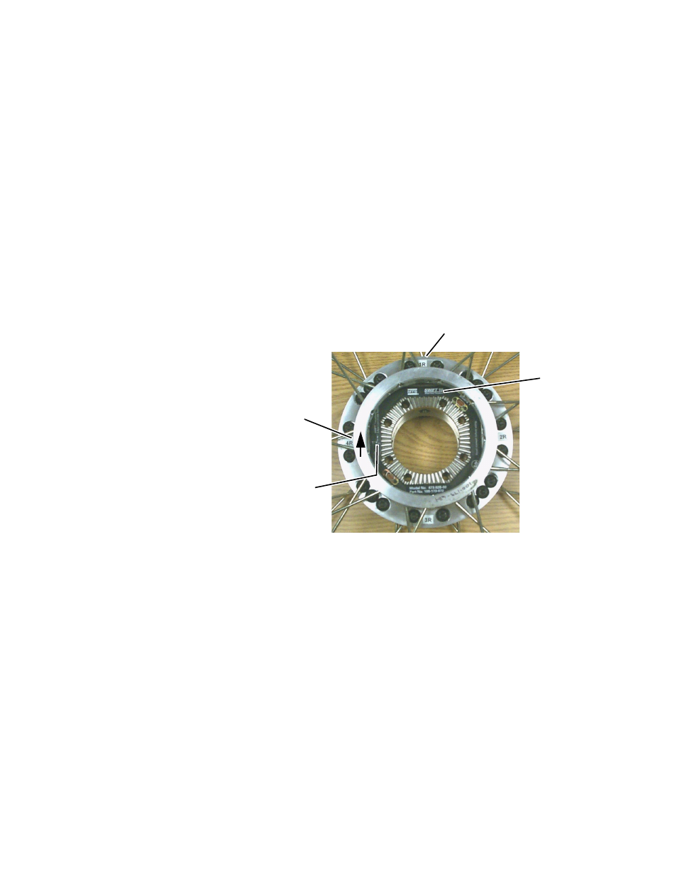
Place the hub adapter labeled 1R on the side of the transducer that you
have determined should face the right side of the vehicle (see the
previous note). Orient the hub adapter such that the bolt holes on either
side of the label 1R align with the bolt holes above the label SWIFT 10
on the transducer (see the next figure).
Place the hub adapter labeled 1L on the side of the transducer that you
have determined should face the left side of the vehicle. Ensure that the
label 1L is directly opposite the label 1R.
B. Secure each hub adapter to the transducer using twenty M8 Torx
fasteners.
Lubricate the threads and under the head of each fastener with
Molykote g-n paste.
C. Following the outer bolt pattern sequence shown in the figure on
page
65
, torque the twenty M8 bolts (1 through 20) on one side of the
transducer to the value for the first increment shown in the table on
page 65
.
Repeat this step for the twenty fasteners on the other side of the
transducer.
D. Repeat Step 4C for the final increment.
E.
Install the spokes in the rim and spoke hub adapter.
Hand tighten the spokes using the tools provided. Final tensioning and
trueing the spokes for lateral and radial runout will be performed later.
For future reference,
mark this spot to
identify the Z-axis
direction as shown on
the axes icon on the
transducer
Z
Location of
Axis Icon
1R Label
SWIFT 10
Label