6 description of the digital inputs and outputs – Lenze 8615E User Manual
Page 34
32
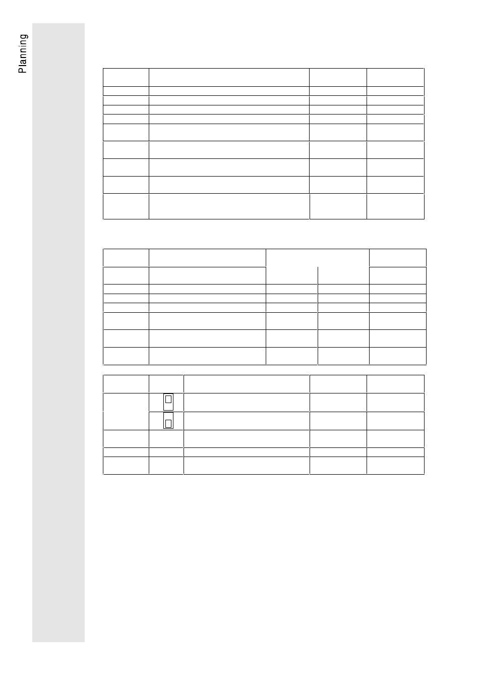
5.2.6 Description of the digital inputs and outputs
Digital inputs
Terminal
Use
(factory setting)
Signal for
activation
Programming see
page
20
Supply voltage 15V, 100mA
-
21
Remove quick stop, CW rotation
HIGH
58
22
Remove quick stop, CCW rotation
HIGH
58
28
Controller enable
HIGH
58
E1
Freely assignable input
(TRIP-set)
HIGH
78ff.
E2
Freely assignable input
(TRIP reset)
HIGH
78ff.
E3
Freely assignable input
(Activate DC injection braking)
HIGH
78ff.
E4, E5,
E6
Freely assignable input
(Enable JOG set-values, seven JOG values)
HIGH
78ff.
E7, E8
Freely assignable input
(Enable additional acceleration and deceleration
times, three ramp times)
HIGH
78ff.
Digital outputs
Terminal
Use
(factory setting)
Message
in the state
Programming see
page
"ready"
"Function
active"
41
Fault indication
−
TRIP
HIGH
LOW
88
44
Ready
−
RDY
HIGH
HIGH
88
45
Pulse inhibit
−
IMP
HIGH
LOW
88
A1
Freely assignable output
(Output frequency < Q
min
threshold)
LOW
LOW
86ff.
A2
Freely assignable output
(Maximum current reached - I
max
)
LOW
HIGH
86ff.
A3
Freely assignable output
(Set-value reached - RFG/O=I)
HIGH
HIGH
86ff.
Terminal
Switch
setting
Use
(factory setting)
Message
Programming see
page
A4
Frequency output
(6 times field frequency 6
⋅
f
d
Pulse train
−
Freely assignable output
(no function)
−
86ff.
39
Ground of the digital inputs and outputs
(external GND)
−
−
40
Internal ground (GND)
−
−
59
Supply input of the digital outputs (24V
ext. or 15V int.)
−
−