5 digital inputs and outputs – Lenze 8615E User Manual
Page 32
30
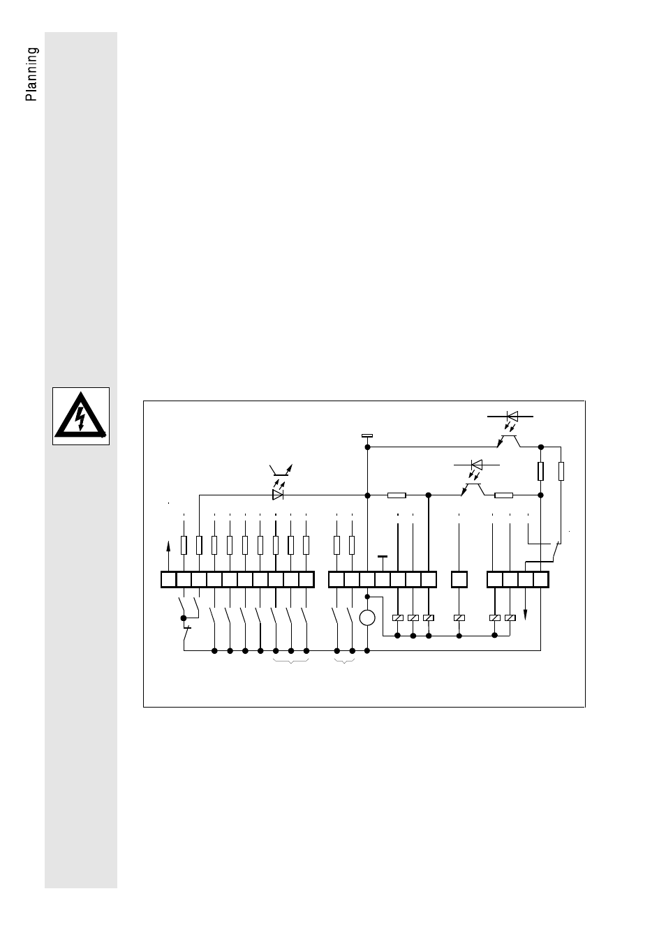
5.2.5 Digital inputs and outputs
The functions for the digital inputs and outputs shown below are
factory-set. To switch the signal cables, only use relays with low-
current contacts. Relays with gold-plated contacts have proven for
this.
All digital inputs and outputs are PLC compatible and are - when
operated with an external voltage supply (24 V) - isolated from the
rest of the control stage. To connect the voltage supply, use
terminals 39 and 59. If there is no external voltage supply, the
internal 15 V-supply can be used.
External voltage supply (24 V)
Inputs:
Input voltage:
0 to 30 V
LOW signal:
0 to 5 V
HIGH signal:
13 to 30 V
Input current:
for 24 V 8 mA per input
Outputs:
Maximum voltage supply:
30 V
Maximum output current:
50 mA per output (external
resistor at least 480
Ω
for 24 V,
e.g. relay, part no. 326 005)
A3
45
40
22
X2
X4
20 21
28 E1 E2 E3 E4 E5 E6
E7 E8
41 44
A1
A2
A4 59
_
X3
39
22k
10R
2.
7k
10k
+
15V 1
00m
A
R
L
GND
GND ext.
+
QSP
Ctrl.
enable
DC brake
JOG
Ti
TRIP-
set/reset
TRIP
RDY
IMP
Qmin
Imax
RFG/O=I
S2
3k
3k
3k
3k
3k
3k
3k
3k
3k
3k
50
m
A
50
m
A
50
m
A
50
m
A
50
m
A
50
m
A
50
m
A
6 x f
d