Wiring the device modules – Lenze E94ASHE Axis Single Drive 32-104A User Manual
Page 77
Wiring the device modules
Function modules
l
77
EDK94SH104 DE/EN/FR/ES/IT 5.1
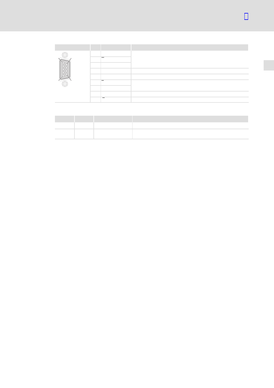
X10
Pin
Designation
Explanation
1
6
5
9
1
B
TTL output signal from encoder or encoder simulation
2
A
3
A
4
+5 V
V
CC
±6 %
5
GND
−
6
Z
TTL output signal from encoder or encoder simulation
7
Z
8
Enable
Digital output signal
SUBD09010
9
B
TTL output signal from encoder or encoder simulation
Displays
Pos.
Colour
Condition
Description
MS
Green
ON
The module is supplied with voltage.
DE
Red
ON
The module is not accepted by the standard device (see notes
given in the documentation for the standard device).
See also other documents in the category Lenze Hardware:
- ESMD smd tmd remote keypad (4 pages)
- EPM Programmer EEPM1RA (114 pages)
- ESMDC (36 pages)
- SMD Frequency Inverter 0.37kW-22kW (116 pages)
- SMD Frequency Inverter: Basic I/O with CANopen 0.25kW-4.0kW (36 pages)
- SMD 0-25kW-4-0kW (112 pages)
- smd Series Drives (32 pages)
- ESV SMV remote keypad H0 (2 pages)
- ESV SMV remote keypad H1 (2 pages)
- SV SMV additional I-O module (14 pages)
- EEPM1RA EPM (26 pages)
- SMVector RS-485 LECOM (29 pages)
- E84AYM10S (4 pages)
- E84AYCET EtherCAT MCI module (109 pages)
- EZAMBKBM (6 pages)
- E84AYCEC (89 pages)
- ERBPxxxRxxxx Brake resistor 200W-300W (134 pages)
- E84AYCPM (115 pages)
- E84AYCEO (165 pages)
- E84AYCER (94 pages)
- E84AVSCx 8400 StateLine C (76 pages)
- EZVxxxx-000 Power supply unit AC 230V 5A-20A (62 pages)
- E84AYCIB (75 pages)
- E82ZWBRB (48 pages)
- EZVxx00−001 Power supply unit AC 400V 5A-20A (64 pages)
- E82ZWBRE (64 pages)
- EZAEBK1001 (94 pages)
- E94AYAE SM301 (134 pages)
- E94AYAE SM301 (74 pages)
- E94AYAE SM301 (140 pages)
- E94AZPS (114 pages)
- E94AYCIB (78 pages)
- E94AYCIB (124 pages)
- E94AZEX100 (84 pages)
- EZS3-xxxA200 Sinusoidal filter 115-150A (44 pages)
- E94AZHA0051 (104 pages)
- E94AZCDM030 (72 pages)
- EZS3-xxxA200 Sinusoidal filter 180-480A (74 pages)
- E94AYCCA (188 pages)
- E94AYCCA (114 pages)
- E94AZHB0101 (104 pages)
- E94AYCPM (114 pages)
- E94AYCPM (125 pages)
- E94AYCET (140 pages)
- E94AYCET (103 pages)