7commissioning of the system – Lenze EtherCAT Controller-based Automation User Manual
Page 41
Lenze · Controller-based Automation · EtherCAT® Communication Manual · DMS 6.4 EN · 04/2014 · TD17
41
7
Commissioning of the system
7.2
Overview of the commissioning steps
_ _ _ _ _ _ _ _ _ _ _ _ _ _ _ _ _ _ _ _ _ _ _ _ _ _ _ _ _ _ _ _ _ _ _ _ _ _ _ _ _ _ _ _ _ _ _ _ _ _ _ _ _ _ _ _ _ _ _ _ _ _ _ _
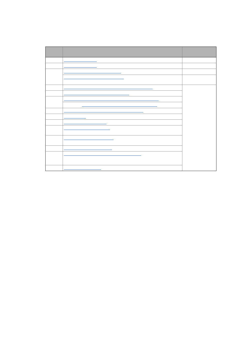
The main commissioning steps are listed in the following table:
Step
Activity
Lenze software to be
used
1.
Installing field devices ( 43)
2.
Create a project folder ( 43)
3.
Commissioning the i700 servo inverter ( 44)
»PLC Designer«
Commissioning other Lenze field devices ( 70)
»Engineer«
/
»EASY Starter«
4.
Creating a PLC program with a target system (Logic/Motion) ( 71)
»PLC Designer«
5.
Configuring the communication parameters ( 73)
6.
Determining the physical EtherCAT configuration (fieldbus scan) ( 75)
If necessary
Importing missing devices / device description files ( 78)
7.
Creating a control configuration (adding field devices) ( 79)
8.
9.
Setting a DC synchronisation ( 87)
10.
Setting SoftMotion parameters ( 92)
Only required for drives with Motion functionality.
11.
Processing EtherCAT I/O mapping ( 95)
Only required for drives that solely have the master functionality (logic bus).
12.
Compiling the PLC program code ( 103)
13.
Logging in on the controller with the »PLC Designer« ( 103)
With the log-in, the fieldbus configuration and the PLC program are loaded into
the Controller.
14.